
Golf ball

a technology of golf ball and ball, applied in the field of golf balls, can solve the problems of loss of distance, increase the distance of travel, and small drag coefficient, and achieve the effect of increasing the distance traveled by the ball

Active Publication Date: 2007-05-24
BRIDGESTONE SPORTS
View PDF7 Cites 16 Cited by
  • Summary
  • Abstract
  • Description
  • Claims
  • Application Information

AI Technical Summary

Benefits of technology

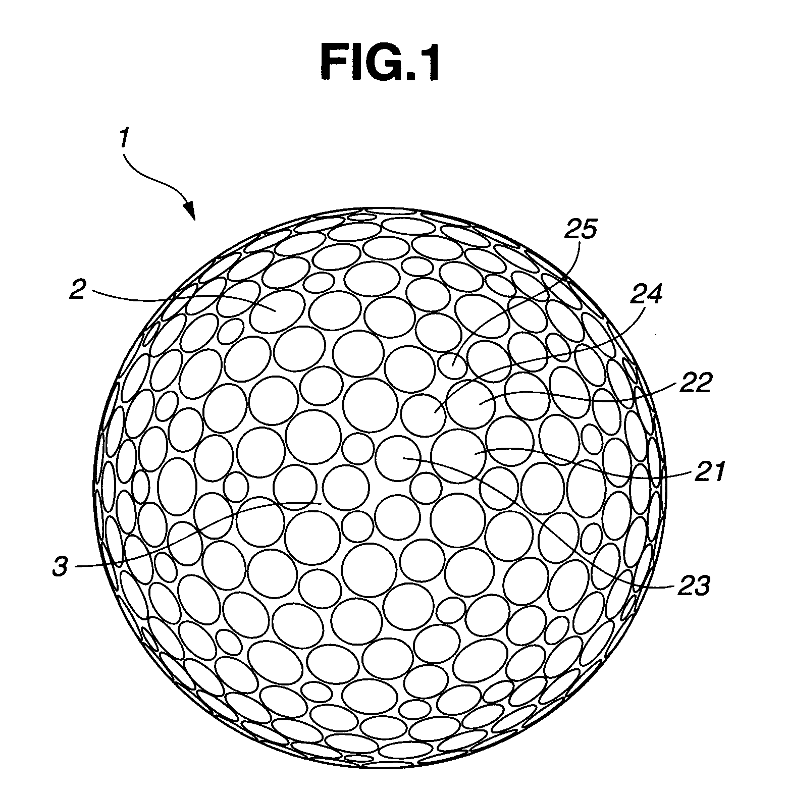
[0005] It is thus an object of the invention to provide a golf ball which, owing to the optimization of such ball characteristics as the total number of dimples arranged on a specific golf ball cover, the combination of large and small dimples, and the density of the dimple arrangement, does not readily lose lift even near the highest point in the trajectory of the ball during flight, and thus can beneficially increase the distance traveled by the ball.
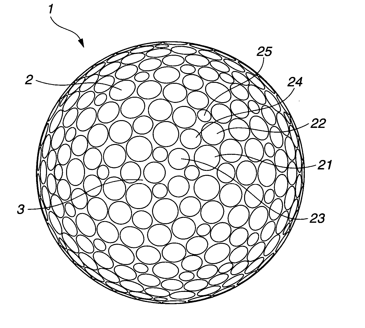
[0006] We have conducted extensive investigations, as a result of which we have found that, with regard to circular dimples arranged on the surface of a golf ball, by using a plurality of dimple types of differing diameter within a fixed range in the total number of dimples and by arranging the dimples so that dimples of a relatively small diameter are included in a given amount and combined to a high density with dimples of a relatively large diameter, the distance traveled by the ball is increased and the flight performance is stabilized.

Problems solved by technology

However, it was later found that a golf ball hit at a low spin and a high launch angle will travel a longer distance.
Under low-spin conditions, the ball that has been hit will have a small coefficient of drag, which tends to increase its distance of travel.
Yet, when the dimples that have been used in earlier golf balls are used unchanged in these more advanced golf balls, a drop occurs due to insufficient lift in the region of diminishing speed after the highest point of the ball's trajectory, resulting in a loss of distance.

Method used


Image

  • Golf ball
  • Golf ball
  • Golf ball

Examples


examples

[0033] The dimple arrangement diagrams, number of dimples, and various parameters of each type of dimple for the golf balls obtained in the respective Examples of the invention and Comparative Examples are presented in Table 1 below. The symbols representing dimple characteristics in the top line of Table 1 are explained below.

Vo

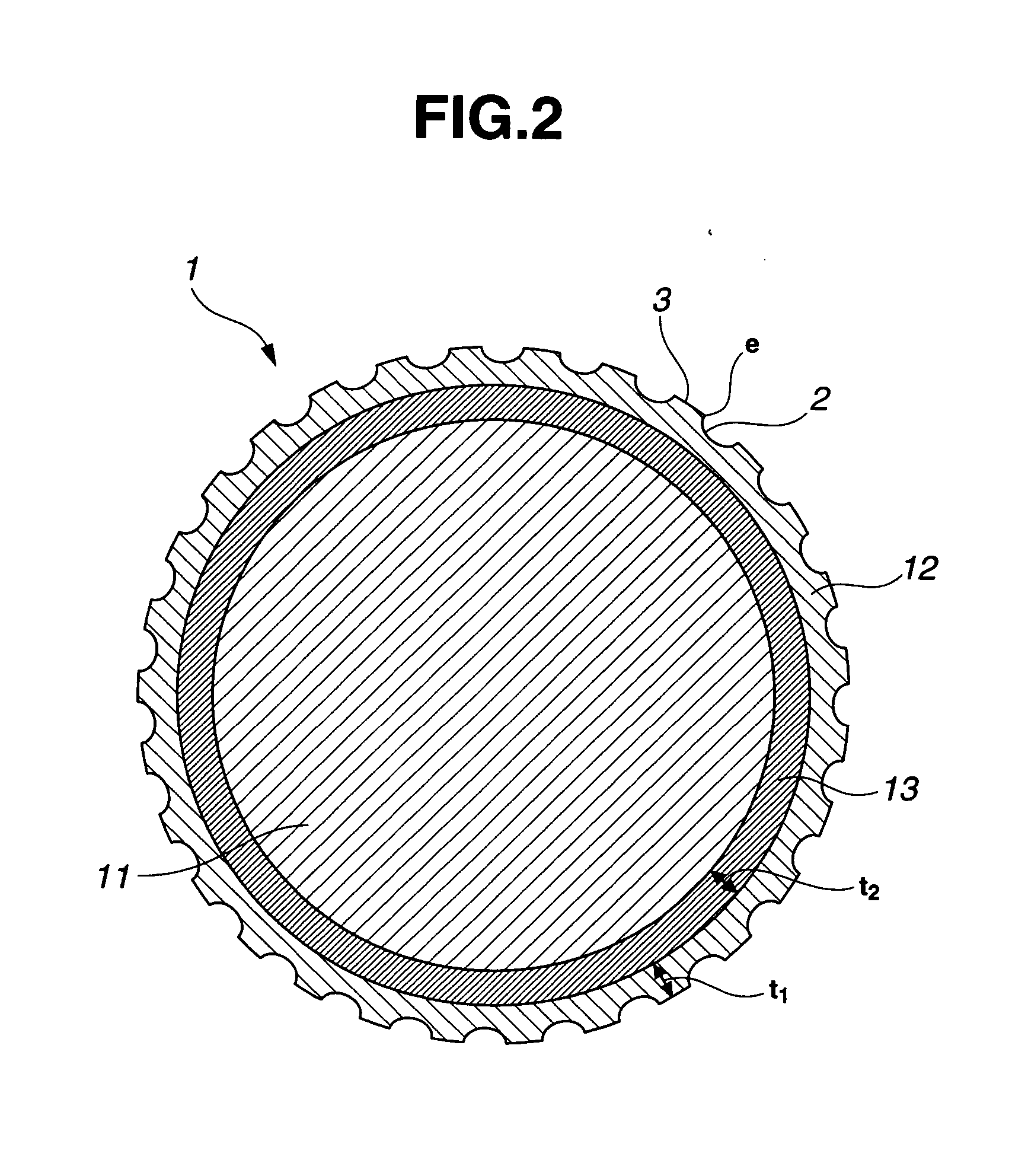
[0034] Referring to FIGS. 3 and 8, Vo is the value obtained by dividing the volume of the dimple space under the planar surface circumscribed by the dimple edge e by the volume of a cylinder whose base is the planar surface and whose height is the maximum depth Dp from the bottom of the dimple to the planar surface. Numerical values within parentheses are averages for all dimples.

Vs

[0035] Vs is the overall volume of a dimple space under the planar surface circumscribed by the dimple edge e. Values in parentheses are the sum of the volumes for all dimples.

r

[0036] The symbol r represents the radius of curvature at the dimple margin (FIG. 3) before a fin...


PUM


Abstract

In a golf ball composed of a resilient solid core and a resin cover which encloses the core and has on an outside surface thereof numerous circular dimples, the cover has a maximum thickness of 0.5 to 1.5 mm and is made of a polyurethane elastomer having a Shore D hardness of 40 to 58; the total number of dimples on the cover is from 390 to 420, of which 40 to 80 are small-diameter dimples with a diameter of 2.0 to 2.7 mm; and the dimples are arranged so that total planar surfaces circumscribed by dimple edges which delineate boundaries between individual dimples and surrounding land areas that form an outermost surface of the ball account for 74 to 84% to an imaginary sphere defined by the surface of the ball having no dimples thereon. The golf ball of the invention does not readily lose lift even near the highest point in the trajectory of the ball when it has been hit, and thus can beneficially increase the distance of travel.

Description

BACKGROUND OF THE INVENTION [0001] The present invention relates to a golf ball having an excellent flight performance. [0002] In the past, to improve both the feel of solid golf balls on impact and their controllability, such balls were optimized for properties such as core and cover hardness under high-trajectory conditions owing to a relatively high spin rate. [0003] However, it was later found that a golf ball hit at a low spin and a high launch angle will travel a longer distance. Hence, greater effort has come to be devoted to increasing the distance of travel in a manner which is in keeping with these findings. With recent advances in golfing equipment such as balls and clubs, designs are being worked out on drivers and other golf clubs built for distance that greatly reduce the amount of backspin taken on by a golf ball when hit. [0004] Under low-spin conditions, the ball that has been hit will have a small coefficient of drag, which tends to increase its distance of travel....

Claims


Application Information

Patent Timeline
Patent Type & Authority Applications(United States)
IPC IPC(8): A63B37/04
CPCA63B37/0004A63B37/0012A63B37/0018A63B37/002A63B37/0021A63B37/0022A63B37/0031A63B37/0033A63B37/0043A63B37/0045A63B37/0006A63B37/0017A63B37/0019A63B37/0065A63B37/0075A63B37/008A63B37/00065
Inventor KASASHIMA, ATSUKISATO, KATSUNORI
Owner BRIDGESTONE SPORTS
Learn More