System and method for downhole operation using pressure activated and sleeve valve assembly

a technology of pressure activated and sleeve valve, which is applied in the direction of drinking water installation, borehole/well accessories, construction, etc., can solve the economic burden of an expensive deepwater infrastructure, the associated cost of millions of dollars, and the inability to complete two or more zones in a single well

Inactive Publication Date: 2007-05-31
SUPERIOR ENERGY SERVICES LLC
View PDF59 Cites 32 Cited by
  • Summary
  • Abstract
  • Description
  • Claims
  • Application Information

AI Technical Summary

Problems solved by technology

While many reservoirs have excellent production potential, they cannot support the economic burden of an expensive deepwater infrastructure.
This requires rig mobilization (with its associated costs running into millions of dollars) to shut off or prepare to produce additional zones from the central production facility.
Another problem with existing technology is its inability to complete two or more zones in a single well while addressing fluid loss control to the upper zone when running the well completion hardware.
In the past, expensive and often undependable chemical fluid loss pills were spotted to control fluid losses into the reservoir after perforating and / or sand control treatments.
A concern with this method when completing upper zones is the inability to effectively remove these pills, negatively affecting the formation and production potential and reducing production efficiency.
Still another problem is economically completing and producing from different production zones at different stages in a process, and in differing combinations.
Certain disadvantages have been identified with the systems of the prior art.
For example, prior conventional isolation systems have had to be installed after the gravel pack, thus requiring greater time and extra trips to install the isolation assemblies.
In addition, the installation of prior systems within the wellbore require more time consuming methods with less flexibility and reliability than a system which is installed at the surface.
Each trip into the wellbore adds additional expense to the well owner and increases the possibility that tools may become lost in the wellbore requiring still further operations for their retrieval.
While pressure actuated valves have been used in certain situations, disadvantages have been identified with such devices.
Thus, systems could not reliably use more than one such valve, since the pressure differential utilized to shift the first valve from the closed position to the open would be lost once the first valve was opened.
Therefore, there could be no assurance all valves in a system would open.

Method used


Image

  • System and method for downhole operation using pressure activated and sleeve valve assembly
  • System and method for downhole operation using pressure activated and sleeve valve assembly
  • System and method for downhole operation using pressure activated and sleeve valve assembly

Examples


Embodiment Construction

[0026] For the purposes of promoting an understanding of the principles of the invention, reference will now be made to the embodiment illustrated in the drawings and specific language will be used to describe the same. It will nevertheless be understood that no limitation of the scope of the invention is thereby intended, such alterations and further modifications in the illustrated device, and such further applications of the principles of the invention as illustrated therein being contemplated as would normally occur to one skilled in the art to which the invention relates.

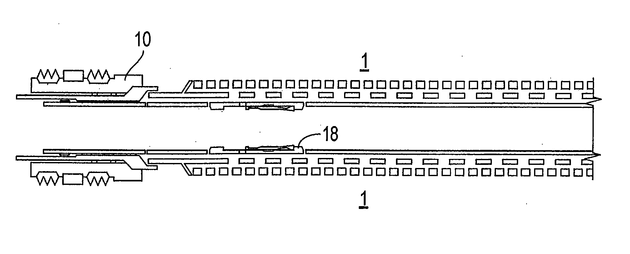
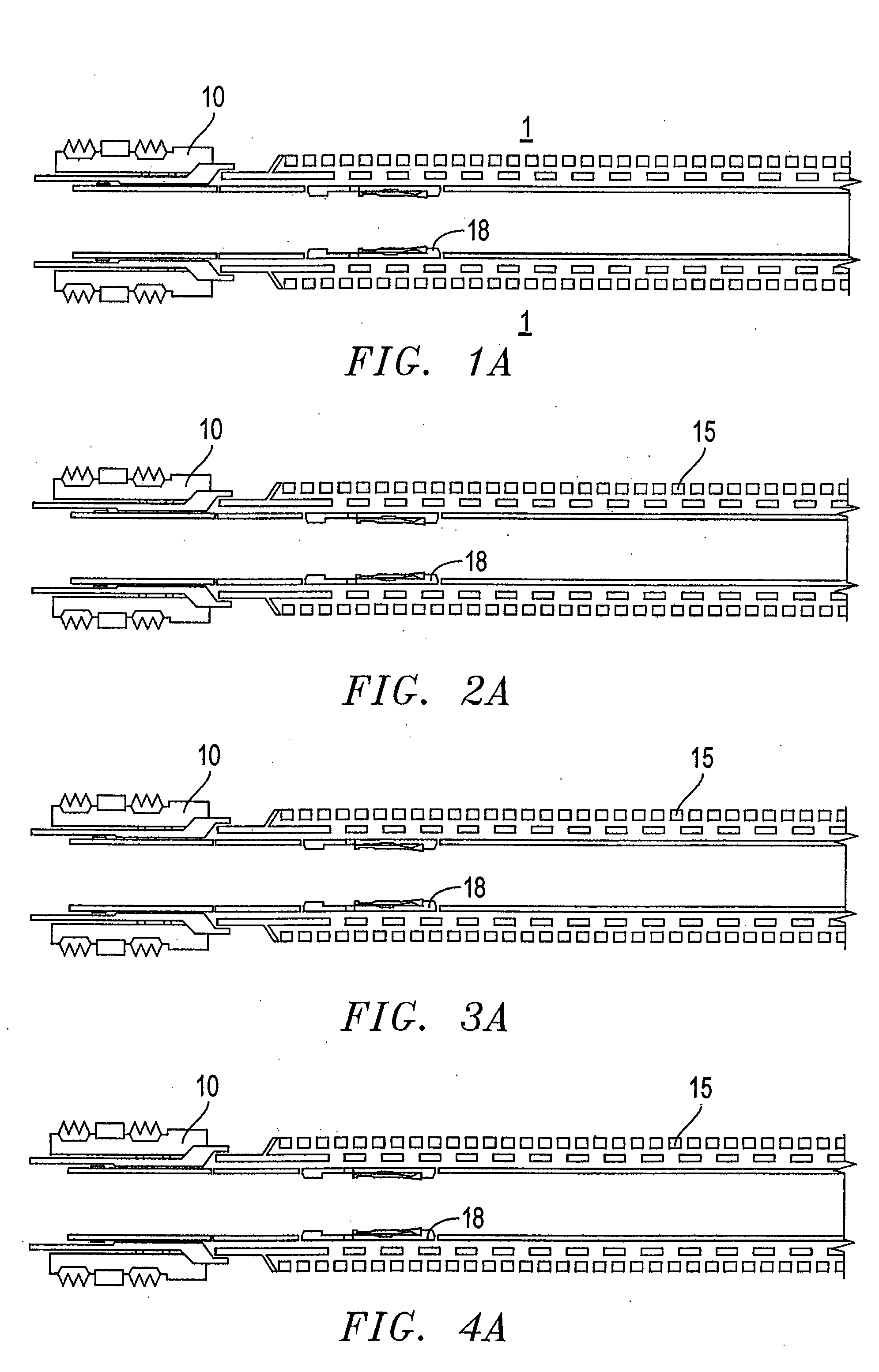
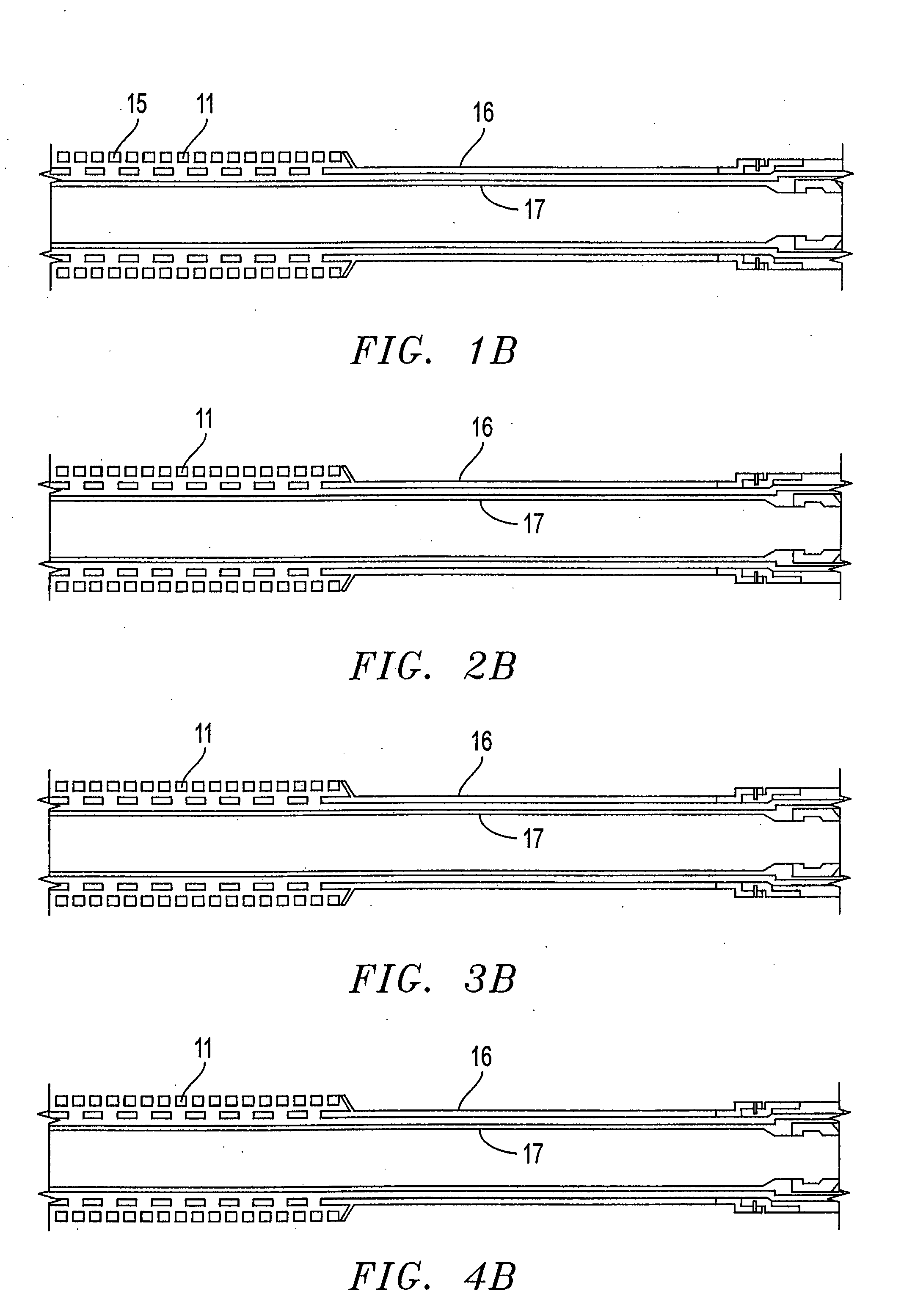
[0027] Referring to FIGS. 1A through 1I, there is shown a system for production over two separate zones. A first isolation string 11 is placed adjacent the first production zone 1. A second isolation string 22 extends across the second production zone 2. The first isolation string 11 enables gravel pack, fracture and isolation procedures to be performed on the first production zone 1 before the second isolatio...


PUM


Abstract

An isolation system for producing oil and gas from one or more formation zones and methods of use are provided comprising one or more pressure activated and tool shiftable valve assemblies. The tool shiftable valve may be actuated before or after actuation of the pressure activated valve.

Description

CROSS-REFERENCE TO RELATED APPLICATIONS [0001] This is a continuing application of U.S. application Ser. No. 10 / 788,833, filed on Feb. 27, 2004 for “System And Method For Downhole Operation Using Pressure Activated Valve And Sliding Sleeve,” now issued as U.S. Pat. No. 7,152,678, and which claims benefit of and priority to U.S. patent application Ser. No. 10 / 004,956, now issued as U.S. Pat. No. 6,722,440, which claims benefit of and priority to U.S. Provisional Application Ser. No. 60 / 251,293, filed Dec. 5, 2000 for “Multi-Zone Completion Strings And Methods For Multi-Zone Completions,” the disclosures and teachings of all of which are hereby incorporated by reference for all purposes.BACKGROUND OF THE INVENTION [0002] The present invention relates to the field of well completion assemblies for use in a wellbore. More particularly, the invention provides a method and apparatus for completing and producing from multiple mineral production zones, independently or in any combination. [...

Claims


Application Information

Patent Timeline
Patent Type & Authority Applications(United States)
IPC IPC(8): E21B34/14E21B43/08E21B34/10E21B43/12E21B43/14
CPCE21B34/102E21B43/08E21B43/088E21B43/12E21B43/14
Inventor TURNER, DEWAYNETRAWEEK, MARVIN BRYCEROSS, RICHARD J.
Owner SUPERIOR ENERGY SERVICES LLC
Why Eureka
Try Eureka