Solenoid valve for different air discharging speeds

Inactive Publication Date: 2007-05-31
TRICORE CORP
View PDF4 Cites 9 Cited by
  • Summary
  • Abstract
  • Description
  • Claims
  • Application Information

AI Technical Summary

Benefits of technology

[0007] The present invention has been accomplished under the circumstances in view. It is one object of the present invention

Problems solved by technology

However, there is still a demand for a slow air discharging speed.
However, conventional dual-speed solenoid valves or low-speed solenoid valves commonly have a complicated st

Method used


Image

  • Solenoid valve for different air discharging speeds
  • Solenoid valve for different air discharging speeds
  • Solenoid valve for different air discharging speeds

Examples


Embodiment Construction

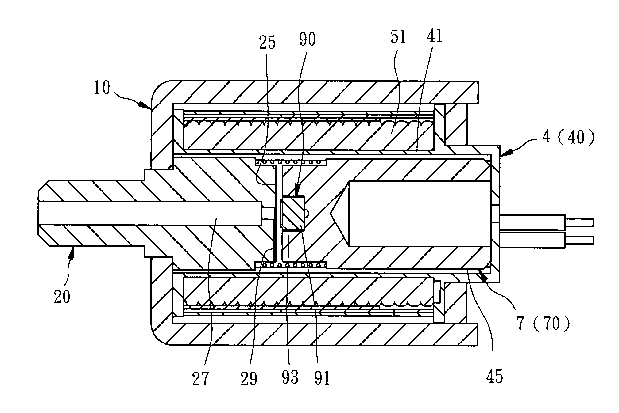
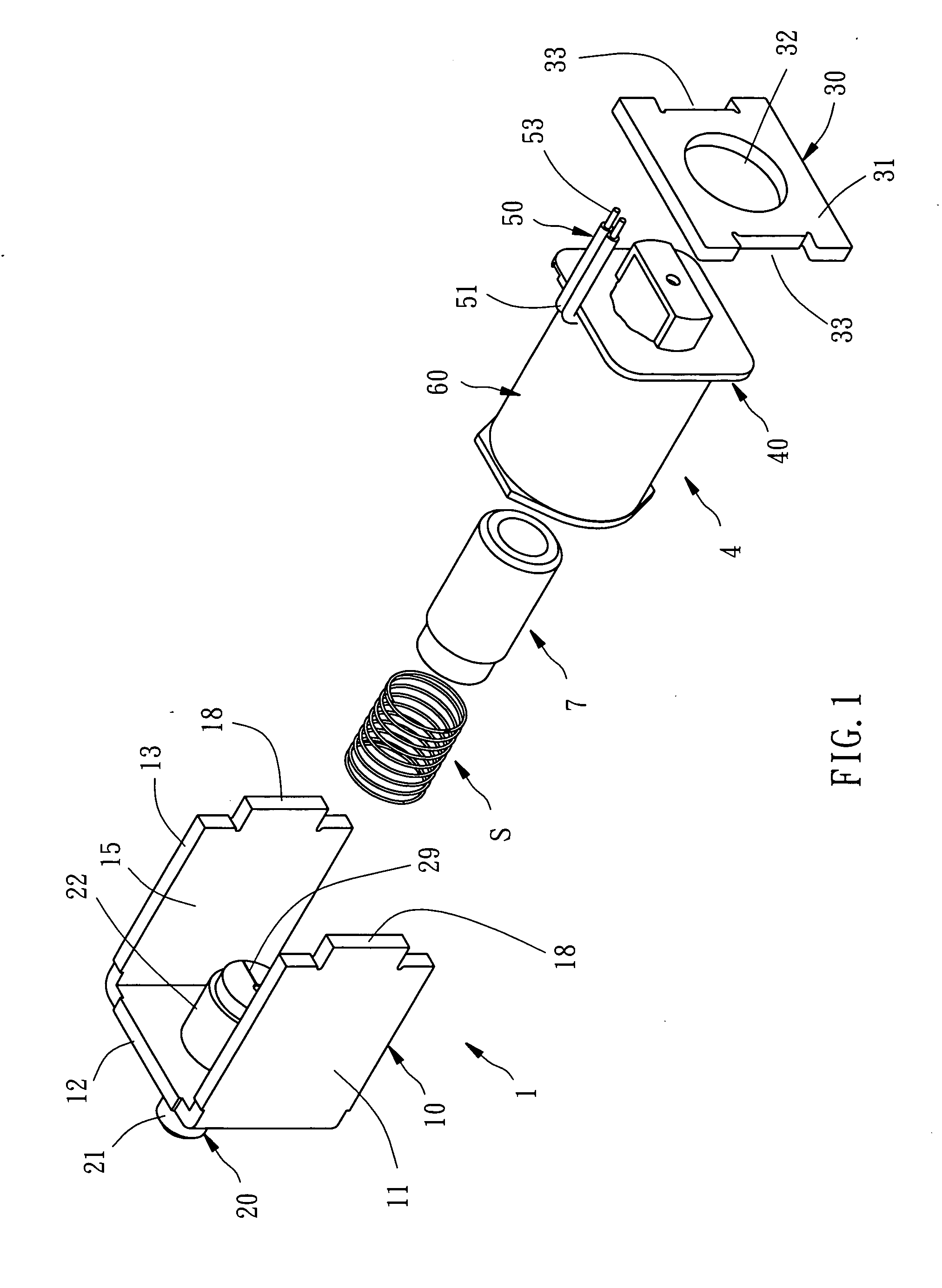
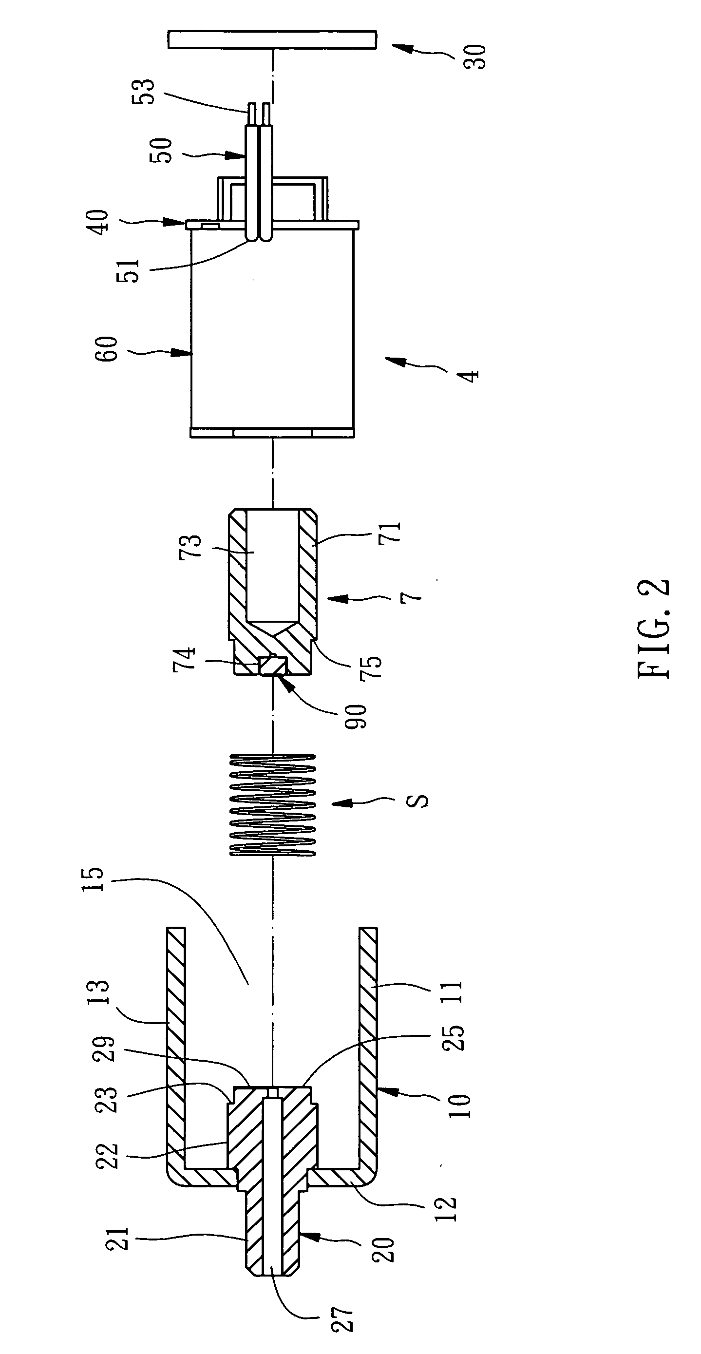
[0022] Referring to FIGS. 1˜5, a solenoid valve in accordance with one embodiment of the present invention is shown controllable to reciprocate. The solenoid valve comprises a holder 1, a coil assembly 4, an actuating rod 7, a seal 90, and a spring member S.

[0023] The holder 1 is comprised of a yoke frame 10, a locating rod 20, and a cover plate 30. The yoke frame 10 is a metal frame having a bottom panel 11, a top panel 13, and a side panel 12 connected between the bottom panel 11 and the top panel 13 at one side. The bottom panel 11, the top panel 13 and the side panel 12 surround a receiving space 15. Further, the bottom panel 11 and the top panel 13 each have a protruding locating block 18. The locating rod 20 is mounted in the side panel 12 of the yoke frame 10, having a first rod section 21 disposed outside the yoke frame 11, a second rod section 22 connected to one end of the first rod section 21, a bearing portion 23 for supporting the spring member S, a stop edge 25 at one...


PUM


Abstract

A solenoid valve includes a holder, which holds a locating rod that defines an air discharging hole for quick discharge of an air, a coil assembly, an actuating rod axially slidably mounted in the coil assembly, a spring stopped between the actuating rod and the locating rod, a flexible seal for sealing the air discharging hole and the coil assembly is energized to move the actuating rod toward the locating rod, and a slow-speed air discharging hole, which may be formed in the locating rod, the actuating rod, or the flexible seal for discharging of an air after blocking of the air discharging hole by the seal.

Description

BACKGROUND OF THE INVENTION [0001] 1. Field of the Invention [0002] The present invention relates to solenoid valves and more particularly, to such a solenoid valve that provides different air discharging speeds. [0003] 2. Description of the Related Art [0004] Conventional solenoid valves for controlling discharging of an air commonly provide only one quick air discharging action, i.e., only rapid air discharging speed. However, there is still a demand for a slow air discharging speed. Therefore, solenoid valves that provide quick and slow air discharging speeds are developed. [0005] However, conventional dual-speed solenoid valves or low-speed solenoid valves commonly have a complicated structure. These complicated solenoid valves may not work accurately during operation. Further, these complicated solenoid valves are difficult to install and, not durable in use. [0006] Therefore, it is desirable to provide a solenoid valve that eliminates the aforesaid drawbacks. SUMMARY OF THE IN...

Claims


Application Information

Patent Timeline
IPC IPC(8): F16K51/00
CPCF16K31/0651F16K31/0658
Inventor HUANG, T. C.
Owner TRICORE CORP
Why Eureka
Try Eureka