Bubble-prevention fast exhaust transfusion device with improved structure
An anti-bubble, infusion set technology, applied in the field of medical infusion sets, can solve the problems of difficult air discharge, cumbersome, time-consuming, etc., and achieve the effects of low production cost, fast exhaust speed, and complete elimination.
- Summary
- Abstract
- Description
- Claims
- Application Information
AI Technical Summary
Problems solved by technology
Method used
Image
Examples
Embodiment 1
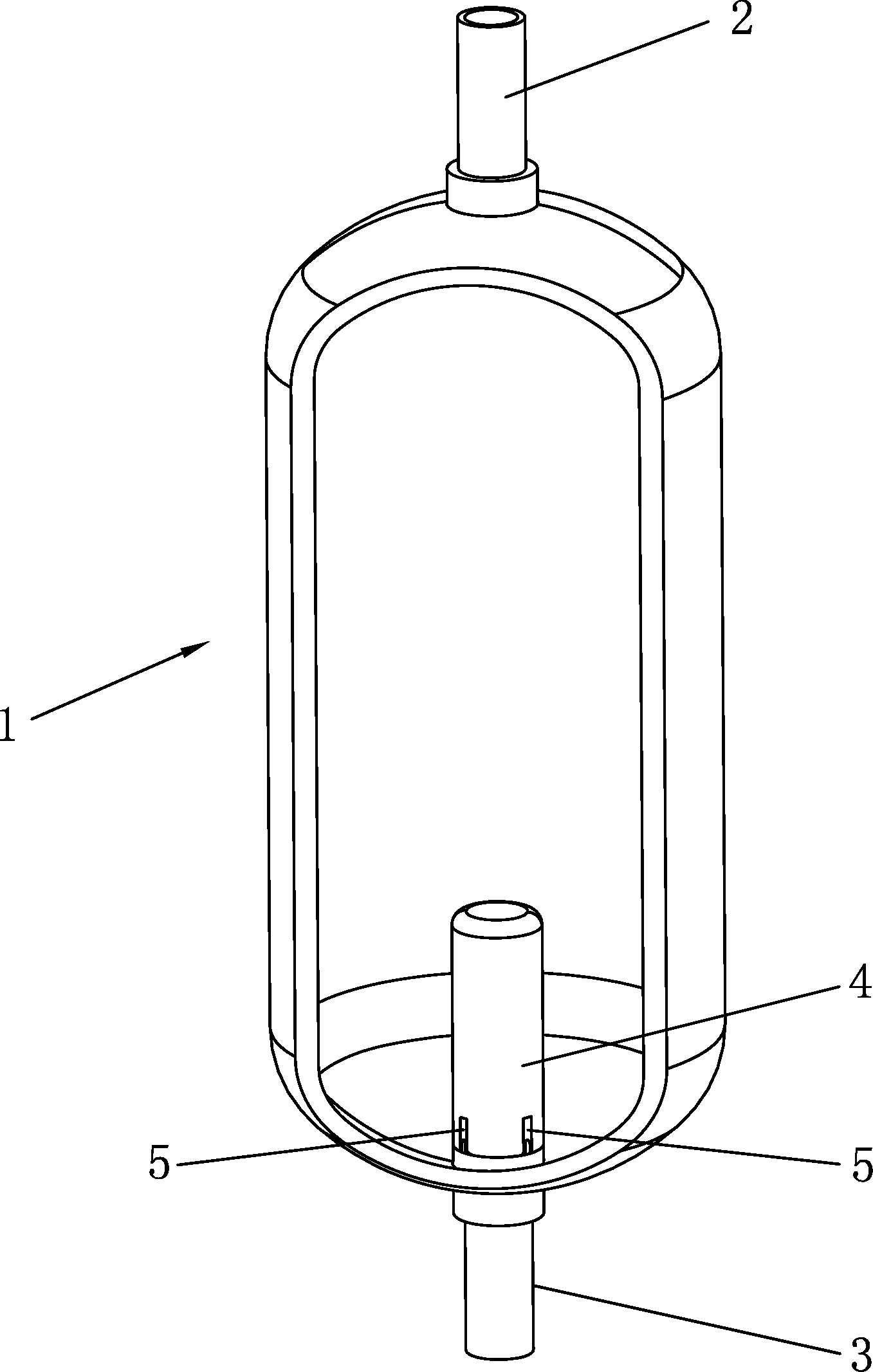
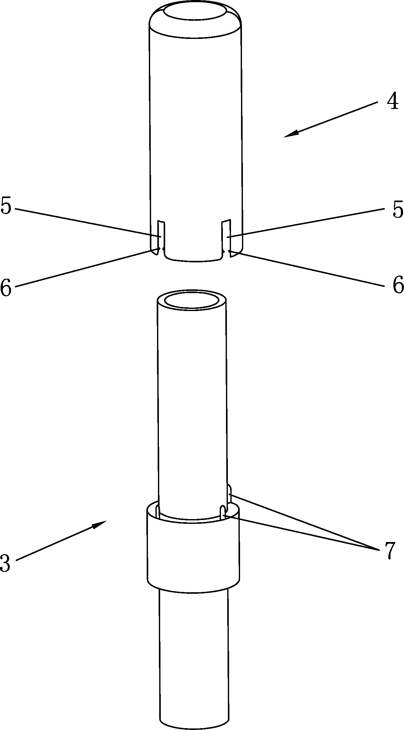
[0035] Such as Figure 1~2 As shown, a structure-improved anti-bubble rapid exhaust infusion set of this embodiment includes a drip funnel 1, the upper end of the drip funnel 1 is connected to the upper drip tube 2, and the lower end of the drip funnel 1 It is connected with the lower dripping pipe 3, and also includes an air insulation cover 4, and the air insulation cover 4 cooperates with the lower dripping pipe 3, and the air insulation cover 4 or the lower dripping pipe 3 is provided with Make the liquid flow into the anti-bubble liquid tank 5 of the lower dropper 3 from bottom to top.
[0036] Specifically, the air insulation cover 4 in this embodiment is provided with an anti-bubble outlet tank 5 that allows liquid to flow into the lower drip tube 3 from bottom to top.
[0037] The working principle of the present invention: during infusion, the liquid drips from the upper dripping tube 2, the dripping liquid will not immediately enter the lower dripping tube 3, and th...
Embodiment 2
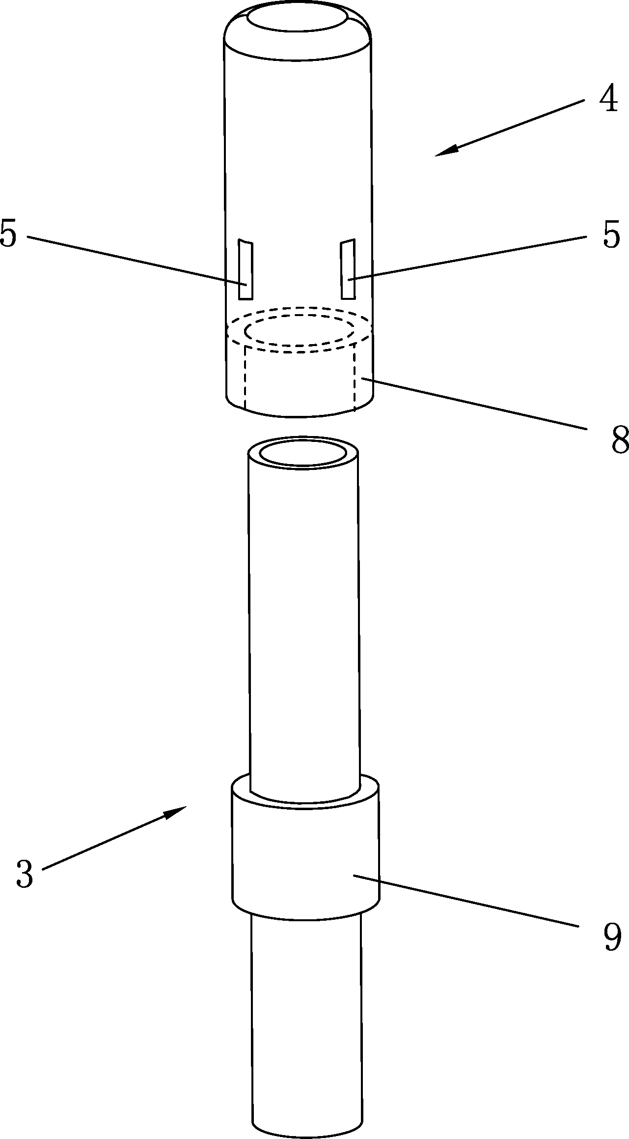
[0043] Such as image 3 As shown, the difference between this embodiment and Embodiment 1 is that: the inner side of the air insulation cover 4 in this embodiment is provided with a groove 8, and the lower dripping tube 3 is provided with a step 9, and the groove 8 cooperates with said step 9. When the present embodiment is in working condition, the air-insulating cover 4 is inverted and covers the outer wall of the lower dripping tube 3, and the air-insulating cover 4 and the lower dripping tube 3 are connected through the groove 8 and the step 9, and the connection is tight. More effectively isolate the air entering the lower dripping pipe 3 to prevent the generation of air bubbles.
[0044] The step 9 is set in the middle of the lower drip tube 3, and the step 9 protrudes outward along the outer wall of the lower drip tube 3, and the step 9 passes through the outlet of the lower end of the dropping funnel 1, and 1 / 2 of the step 9 is set in the dropping funnel 1 , the othe...
Embodiment 3
[0047] Such as Figure 4 As shown, the difference between this embodiment and Embodiment 1 is that the lower dripping pipe 3 described in this embodiment is provided with an anti-bubble outlet tank 5 that allows the liquid to flow into the lower dripping pipe 3 from bottom to top.
[0048] Wherein, the inner side of the air insulation cover 4 is provided with a groove 8, and the lower dropper 3 is provided with a step 9, and the groove 8 cooperates with the step 9. The step 9 is provided with an anti-bubble outlet tank 5 that allows the liquid to flow from bottom to top into the lower drip tube 3, and the lower edge of the air insulation cover 4 is higher than the bottom edge of the anti-bubble outlet tank 5. lower edge. When this embodiment is in working condition, the air insulation cover 4 is inverted and covered on the outer wall of the step 9, 1 / 2 of the step 9 is set inside the dropping funnel 1, and the other 1 / 2 is set outside the dropping funnel 1 to prevent air bubb...
PUM
 Abstract
Description
Claims
Application Information
 - R&D
- Intellectual Property
- Life Sciences
- Materials
- Tech Scout
- Unparalleled Data Quality
- Higher Quality Content
- 60% Fewer Hallucinations
Browse by: Latest US Patents, China's latest patents, Technical Efficacy Thesaurus, Application Domain, Technology Topic, Popular Technical Reports.
© 2025 PatSnap. All rights reserved.Legal|Privacy policy|Modern Slavery Act Transparency Statement|Sitemap|About US| Contact US: help@patsnap.com


