

Device for increasing the bleeding rate of a pneumatic control valve
A technology of exhaust speed and regulating valve, which is applied in the direction of valve operation/release device, valve device, control valve and air release valve, etc. gas velocity etc.
- Summary
- Abstract
- Description
- Claims
- Application Information
AI Technical Summary
Problems solved by technology
Method used
Image

Examples
Embodiment Construction
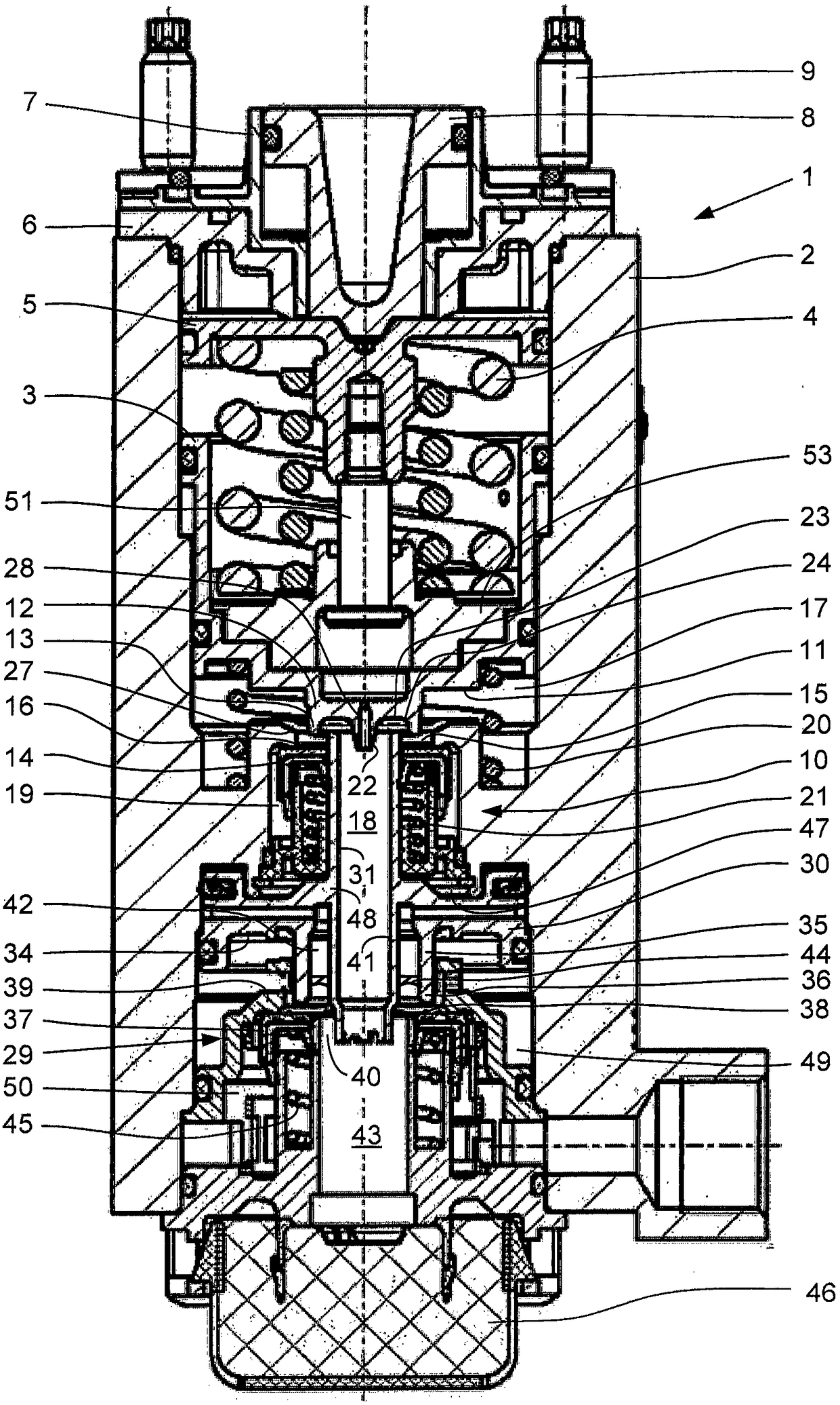
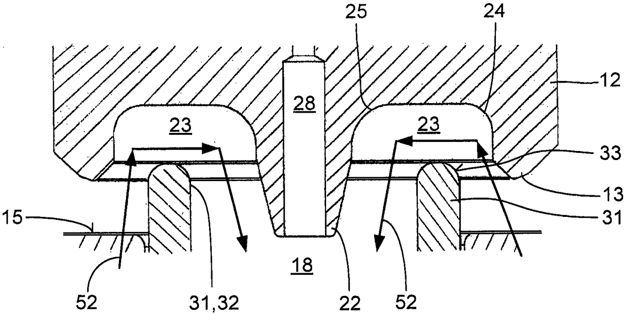
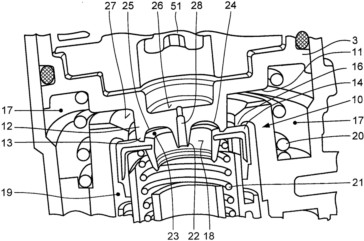
[0018] A regulating valve 1 designed as a brake value indicator for a dual-circuit brake system of a motor vehicle has a housing 2 in which a first valve piston 3 is guided in a sealing manner. The plunger 8 is axially guided on the housing cover 6 in a hollow-cylindrical guide 7 . The housing cover 6 together with the guide 7 is screwed onto the housing 2 by means of fastening screws 9 . Arranged below the underside 11 of the first valve piston 3 is a first valve system 10 comprising a cylindrical projection 12 and an annular sealing seat 13 arranged on the free end of the projection. The first valve piston 3 of the first valve piston 3, the annular first plate valve 14 with the radial sealing surface 15, and the annular sealing seat 13 having a diameter larger than that on the cylindrical protrusion 12 of the first valve piston 3 A large, immovable annular first seal seat 16.
[0019] The cylindrical protrusion 12 on the first valve piston 3 and the immovable, annular firs...
PUM
 Abstract
Description
Claims
Application Information