Inflator second stage combustion control

Active Publication Date: 2007-05-31
AUTOLIV ASP INC
View PDF11 Cites 34 Cited by
  • Summary
  • Abstract
  • Description
  • Claims
  • Application Information

AI Technical Summary

Benefits of technology

[0010] The present embodiments relate to an airbag system that may be used on a vehicle interior. Like other airbag systems, this present system includes an airbag to inflate in front

Problems solved by technology

When an accident occurs, the inflator will rapidly produce a large quantity of gas that is then channeled into the airbag.
As accidents occur quickly, this inflation of the airbag must occur very rapidly-i.e., generally within approximately 100 or 150 milliseconds.
Unfortunately, there are significant problems associated with currently known dual-stage inflators (such as the type disclosed in the above-referenced patents).
For example, such combustion at atmospheric pressure generally results in inc

Method used


Image

  • Inflator second stage combustion control
  • Inflator second stage combustion control
  • Inflator second stage combustion control

Examples


Embodiment Construction

[0037] The presently preferred embodiments of the present invention will be best understood by reference to the drawings, wherein like parts are designated by like numerals throughout. It will be readily understood that the components of the present invention, as generally described and illustrated in the figures herein, could be arranged and designed in a wide variety of different configurations. Thus, the following more detailed description of the embodiments of the present invention, as represented in the Figures, is not intended to limit the scope of the invention, as claimed, but is merely representative of presently preferred embodiments of the invention.

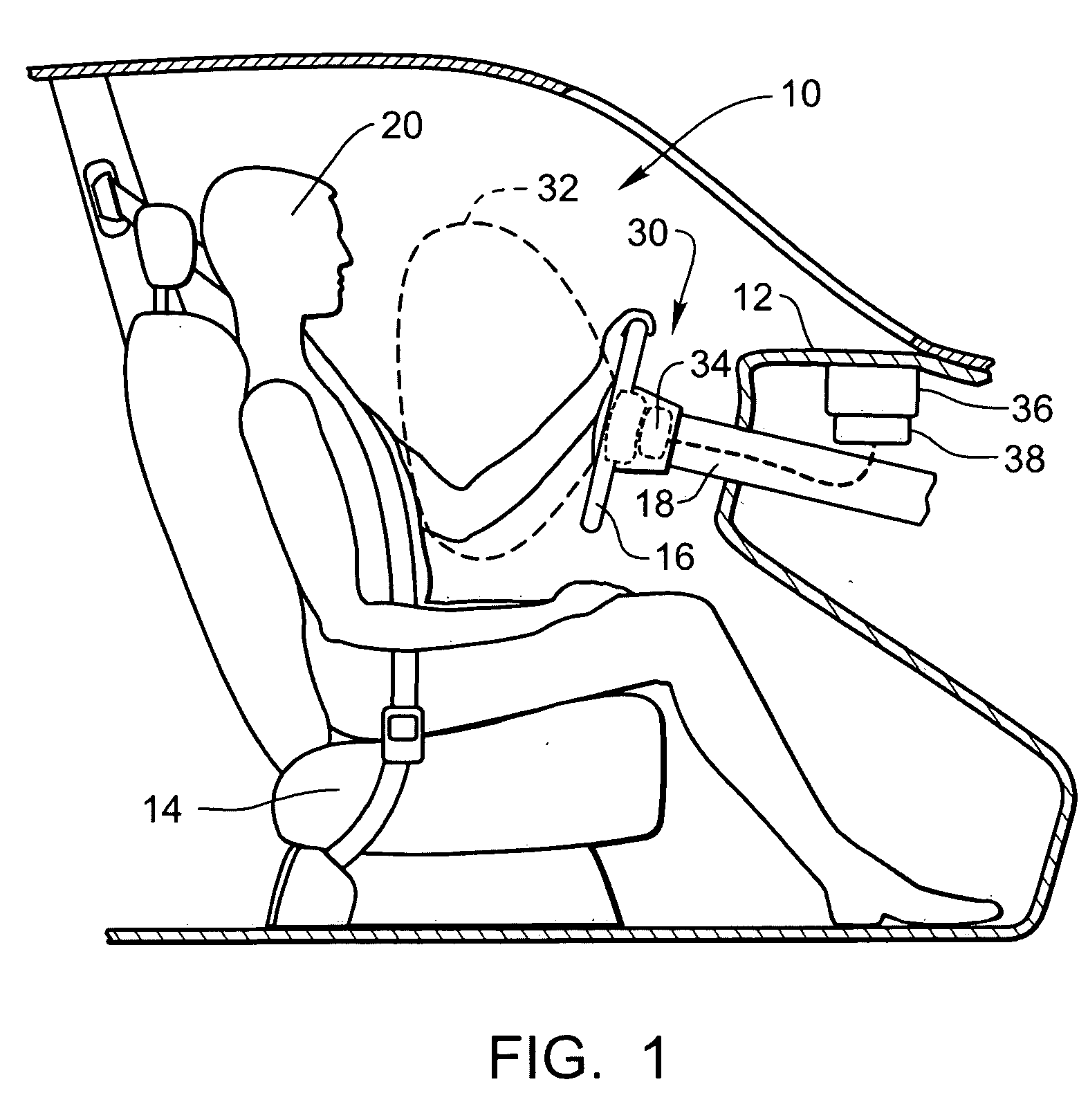
[0038] Referring now to FIG. 1, a cutaway sectional view of an example of a vehicle interior 10 is illustrated. The vehicle interior 10 includes a dashboard 12, an occupant seat 14, a steering wheel 16, and a steering column 18. The steering column 18 operates to support the steering wheel 16 and connect the steering wheel 16...


PUM


Abstract

A new type of airbag inflator that may be used in an airbag system is disclosed. The inflator will generally include a housing and two initiators. Accordingly, the inflator is a “dual-stage” inflator. The two stages are disposed within the housing. The second initiator is disposed within a second stage generant cup. A cap is also used to engage the second stage cup. The cap maintains seated engagement with the second stage cup, even during deployment of the second stage. The second stage will also include one or more perforations, which constitute openings through which gas may flow. When the second initiator is in the unactuated state, these perforations will be isolated from the generant by the cap. Actuation of the second initiator unseals the one or more perforations but does not unseat the cap from the cup, due to constraints put in place to prevent such unseating.

Description

BACKGROUND OF THE INVENTION [0001] 1. Technical Field [0002] The present invention relates to airbag inflators. More specifically, the present invention is a new type of airbag dual-stage inflator that may be used with vehicle airbag systems. [0003] 2. Description of the Prior Art [0004] Vehicle airbag systems are known in the art and have been credited with greatly increasing the overall safety of motor vehicles. Specifically, these airbag systems are designed such that during an accident, one or more airbags will be rapidly inflated and will be positioned between the vehicle occupant and the hard surfaces of the vehicle interior. These inflated airbags will inhibit the vehicle occupant from impacting the interior surfaces of the vehicle and will thus greatly reduce the likelihood that the occupant will experience significant injuries in the crash. [0005] As is known in the art, airbag systems will generally include an inflator that is capable of rapidly producing a large quantity ...

Claims


Application Information

Patent Timeline
IPC IPC(8): B60R21/26
CPCB60R21/2644B60R2021/2633B60R2021/2648
Inventor HOFFMAN, ISAACRASMUSSEN, KIRKSMITH, BRADLEY W.
Owner AUTOLIV ASP INC
Why Eureka
Try Eureka