Display driver and electronic equipment

a technology of electronic equipment and driver, applied in the direction of instruments, static indicating devices, etc., can solve the problems of increasing power consumption, electric power consumption, slow cholesteric liquid crystal rewriting rate, etc., and achieve the effect of preventing harmful effects

Inactive Publication Date: 2008-11-20
SEIKO EPSON CORP
View PDF15 Cites 21 Cited by
  • Summary
  • Abstract
  • Description
  • Claims
  • Application Information

AI Technical Summary

Benefits of technology

[0006]The relationship between the selection voltage and the reflectance of the liquid crystal is affected by temperature. FIG. 8 schematically shows temperature dependency of reflectance—selection voltage curve. In FIG. 8, the horizontal axis represents selection voltages while the vertical axis represents reflectance. Here, the reflectance shows a relative brightness, assuming that a reflective brightness of a standard white plate as a reference is 100%. The cholesteric liquid crystal appears closer to white with increased reflectance, while the cholesteric liquid crystal appears closer to black with decreased reflectance. To a pixel whose tone is black, a voltage V1, which is black selection voltage, is applied. To a pixel whose tone is white, a voltage V2, which is a white selection voltage, is applied. FIG. 8 shows an example of drive parameters which are optimized for 25° C. For example, at 29° C., by applying white selection voltage V2, the reflectance of the cholesteric liquid crystal corresponds to not white, but black. This means the system cannot perform normal display at 29° C. On the contrary, in a temperature range of 24-26° C., by application of the white selection voltage V2, the reflectance corresponds to white, and application of the black selection voltage V1, the reflectance corresponds to white. In this temperature range, the system can display white and black correctly. In this case, a temperature margin is 24-26° C. Here, the term “temperature margin” refers to a temperature range in which the system can display correctly black and white.
[0008]The invention provides technology for preventing harmful effects caused by the expansion of the temperature margin.

Problems solved by technology

However, the cholesteric liquid crystal has a demerit in that the rewriting rate of the cholesteric liquid crystal is slower than the conventional liquid crystal.
However, this approach has three problems.
(i) The first problem is a problem caused by a passive matrix system.
(ii) The second problem is a problem of electric power consumption.
This means an increase in power consumption.
(iii) The third problem is a problem of multi-level tone display.

Method used


Image

  • Display driver and electronic equipment
  • Display driver and electronic equipment
  • Display driver and electronic equipment

Examples


first embodiment

1. First Embodiment

[0046]1-1. Configuration

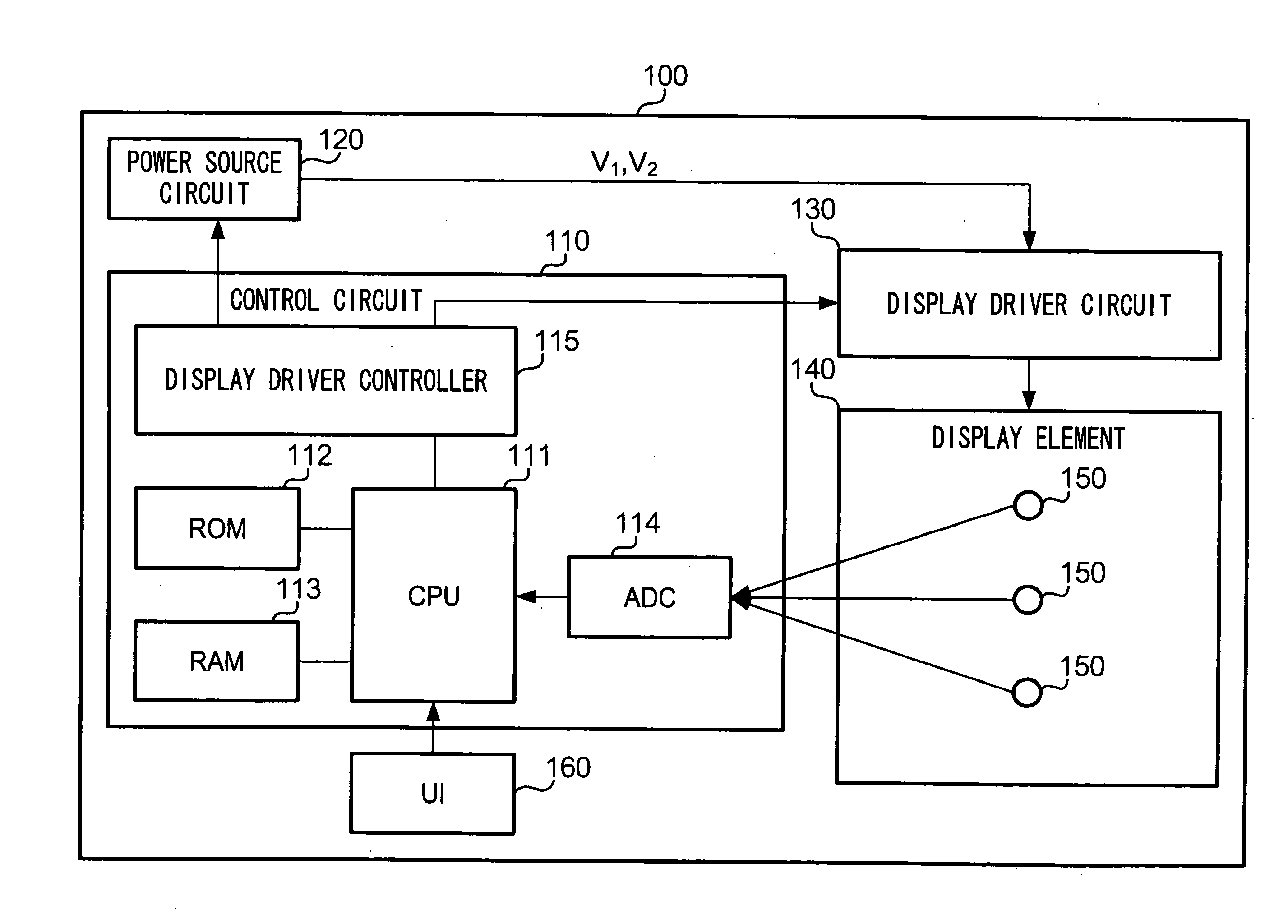
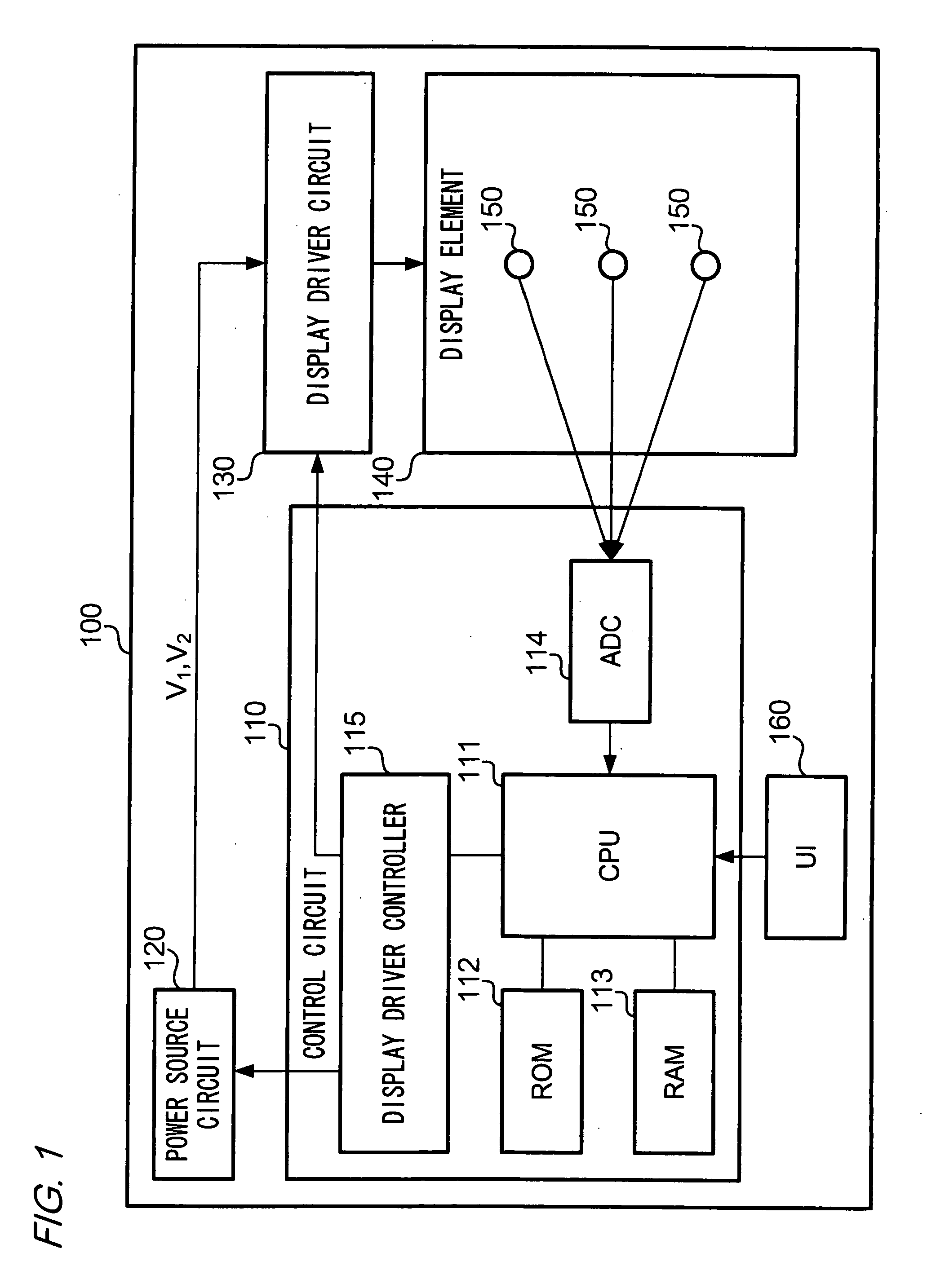
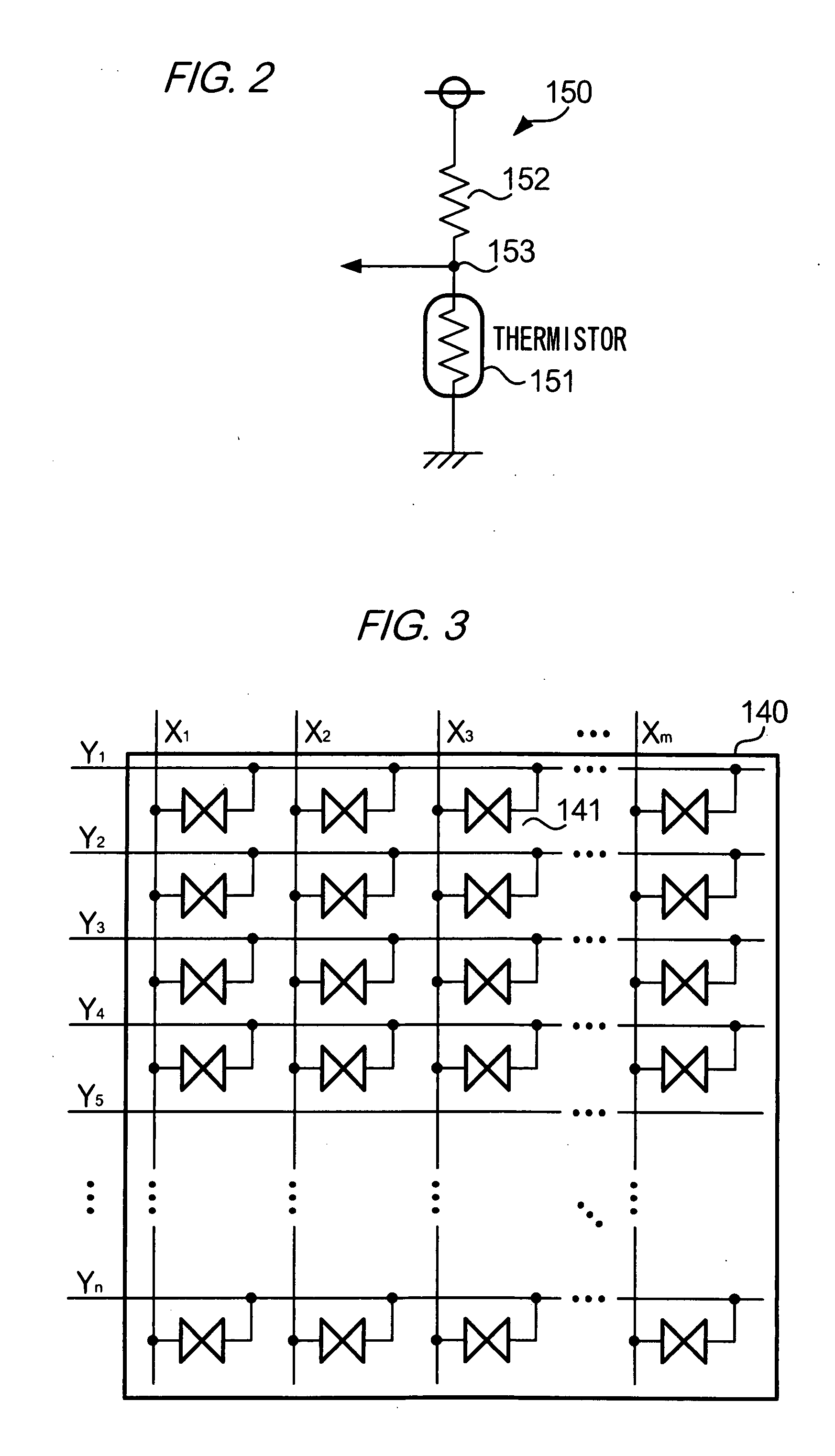
[0047]FIG. 1 shows a configuration of an information processing device 100 in accordance with the first embodiment. The information processing device 100 is electronic equipment that has a function to display a character or an image in response to inputted data. A control circuit 110 controls elements of the information processing device 100. A power source circuit 120 supplies power for driving a display element 140. A display driver circuit 130 outputs a signal for driving the display element 140, under the control of the control circuit 110. In other words, the display driver circuit 130 drives the display element 140. The display element 140 is a display element having an electro-optical layer. The display element 140 has plural temperature sensors 150. A temperature sensor 150 outputs a signal showing its temperature. UI 160 is a user interface by which a user inputs an instruction to the information processing device 100. The UI 160 i...

second embodiment

2. Second Embodiment

[0069]Now, a second embodiment of the invention will be described. In the description of the second embodiment, features common with the first embodiment will be omitted. In addition, the same reference numerals will be used for elements common with the first embodiment.

[0070]FIG. 10 shows a configuration of an information processing device 200 in accordance with the second embodiment. A temperature data storage circuit 210 stores temperature outputted from the temperature sensor 150. The temperature data storage circuit 210 has the following configuration in detail. An ADC 211 is a circuit which converts an analog signal into a digital signal. A PLD (Programmable Logic Device) 212 is a device that stores in the RAM 213 temperature shown by the digital signal outputted from the ADC 211. To the temperature data storage circuit 210, electric power is supplied via a path different from that for the other circuits (the control circuit 110 or the display driver circui...

third embodiment

3. Third Embodiment

[0076]Now, a third embodiment of the invention will be described. In the description of the third embodiment, features common with the first embodiment will be omitted. In addition, the same reference numerals will be used for elements common with the first embodiment.

[0077]FIG. 12 shows a configuration of an information processing device 300 in accordance with the third embodiment. An IR (infrared rays) sensor 310 is a sensor that detects infrared rays. A thermopile is used as the IR sensor 310. The thermopile is a device that generates electromotive force in response to energy of the received infrared rays. In other words, the thermopile outputs a voltage in response to an intensity of the received infrared rays. The IR sensor 310 is mounted on the information processing device 300 at a position near the display element and the same side of the display element. In addition, the IR sensor 310 is exposed. For example, the IR sensor 310 is mounted on a casing of th...


PUM


Abstract

A display driver for driving a display element includes an electro-optical layer to which a drive voltage is applied, the drive voltage being a voltage corresponding to a scanning voltage and a data voltage, the scanning voltage being a voltage applied to a scanning electrode, the data voltage being a voltage applied to a data electrode. The display driver includes: a display driver circuit configured to apply the drive voltage to the electro-optical layer, the drive voltage corresponding to one of at least two operation modes including a first drive mode and a second drive mode, the first drive mode having a first temperature range for representing two tones, the second drive mode having a second temperature range for representing two tones, the first temperature range and the second temperature range being different from each other; an input interface configured to input temperature information, the temperature information being information relating to temperature of the display element; and an operation mode determining unit configured to determine operation mode of the display driver circuit on the basis of the temperature information.

Description

[0001]The entire disclosures of Japanese Patent Applications No. 2006-212780 filed on Aug. 4, 2006, No. 2006-222567 filed on Aug. 17, 2006, and No. 2007-151834 filed on Jun. 7, 2007 are expressly incorporated by reference herein.BACKGROUND[0002]1. Technical Field[0003]The present invention relates to compensating temperature dependency during driving of a display element having image-retaining (bistable) liquid crystal.[0004]2. Related Art[0005]Image-retaining (bistable) liquid crystal such as cholesteric liquid crystal is used as a display medium suitable for a device such as a so-called electronic book or electronic paper. The cholesteric liquid crystal has an advantage in that it can maintain a display without application of a voltage. However, the cholesteric liquid crystal has a demerit in that the rewriting rate of the cholesteric liquid crystal is slower than the conventional liquid crystal. DDS (Dynamic Drive Scheme) is known as a technology by which the rewriting rate of th...

Claims


Application Information

Patent Timeline
Patent Type & Authority Applications(United States)
IPC IPC(8): G09G3/36
CPCG09G3/3651G09G2310/06G09G2320/041
Inventor MUTO, KOTASAWADA, MUNENORI
Owner SEIKO EPSON CORP
Why Eureka
Try Eureka