Operation method and purging system for a hydrogen demand/delivery unit in a fuel cell system

a technology of hydrogen demand and purging system, which is applied in the direction of liquid fuel engine, cell components, electrochemical generators, etc., can solve the problems of systemic accumulation of condensate, difficult sealing, and similar problems, and achieve the effect of preventing the operation or damage of certain components

Inactive Publication Date: 2008-04-08
GM GLOBAL TECH OPERATIONS LLC
View PDF15 Cites 20 Cited by
  • Summary
  • Abstract
  • Description
  • Claims
  • Application Information

AI Technical Summary

Benefits of technology

[0002]In the anode cycle of a low-temperature fuel cell system, especially in so-called PEM fuel cells which are fed with gaseous hydrogen or a hydrogen-rich synthetic gas as fuel, water accumulates in the form of moisture or condensate. This water is formed during the catalytically promoted reaction of protons supplied by the hydrogen, which diffuse through the membrane of the fuel cells, with the air oxygen which is supplied to the cathode sides of the fuel cells, i.e. in the process which is also responsible for the desired generation of current. The water generated on the cathode sides of the fuel cells moistens in a desirable way the membranes of the fuel cells, and part of the water diffuses, together with nitrogen from the fed-in air, through the membrane and in this way passes over to the anode side of the fuel cells. In many fuel cell systems, in addition, water is fed directly to the anode sides of the fuel cells by moistening the fuel in order to assure the desired relative humidity in the anode cycle. The water present in the anode cycle which is partly present in the form of vapor and partly in liquid form freezes at ambient temperatures below 0° C. and can prevent the operation of or damage certain components such as, e.g., a recirculation pump provided for the recirculation of hydrogen or a water separator provided in the anode cycle. Similar problems can also arise elsewhere in a fuel cell system, for example, in a water separator in the cathode cycle of the fuel cell system. The process according to the invention can therefore also be utilized there.
[0004]The objective of the invention is to devise a process or a fuel cell system of the type mentioned initially in which the harmful effects of the accumulating condensate at temperatures below the freezing point can be avoided.
[0010]In order to utilize the dry scavenging gas efficiently, according to the invention, it is advantageous to estimate the quantity of water still present in the anode cycle when switching off the fuel cell system and only to use the necessary quantity of dry scavenging gas for expelling or drying out the quantity of water vapor present. This represents an economical procedure.
[0017]It can be advantageous to conduct a process which is characterized by the fact that the quantity of scavenging gas and / or the duration of the scavenging with dry scavenging gas is selected so as to drive part of the quantity of water present that can be collected, e.g., by a collecting process, out of the anode cycle and in order to remove from the anode cycle a second partial quantity of water by a drying process.
[0018]If the component is so designed that the liquid water present there collects in a region determined in advance then the removal of the liquid water from this region can be accomplished relatively simply and economically, e.g., by having the scavenging gas drive all of the liquid water present in this region out of it. For example, a drain valve can be provided in the immediate proximity of this region which is opened by the control system at the time of the scavenging process in order to drive the collected water out of the system. In this way then only a small residual quantity of water vapor would remain which is removed from the system by a drying process. Here also the dry scavenging gas is used economically.
[0023]The scavenging gas at any rate must be dry, behave inertly with respect to the materials in the anode cycle of the fuel cell system and cannot represent a safety risk when mixed with hydrogen. The use of air as a scavenging gas has the advantage that it is present in the environment in an unlimited quantity. Hydrogen is conveyed anyway as a propellant with the vehicle containing the fuel cell system and inert gases such as N2, argon or helium can easily be conveyed in small quantities. Since these gases also occur in the air, they are suitable as scavenging gases since they do not cause air pollution.

Problems solved by technology

Similar problems can also arise elsewhere in a fuel cell system, for example, in a water separator in the cathode cycle of the fuel cell system.
These are functionally related and cannot be avoided.
The necessary sealing to the outside can be achieved, but it is scarcely possible to seal, for example, the motor of the recirculation pump with respect to the pump itself since the hydrogen-containing gases are capable of penetrating even through the smallest gaps.
The generation of water vapor during the operation of a PEM fuel cell is inevitable and the water vapor always generated in the system under suitable temperature conditions necessarily leads to the systematic accumulation of condensate.

Method used


Image

  • Operation method and purging system for a hydrogen demand/delivery unit in a fuel cell system
  • Operation method and purging system for a hydrogen demand/delivery unit in a fuel cell system
  • Operation method and purging system for a hydrogen demand/delivery unit in a fuel cell system

Examples


Embodiment Construction

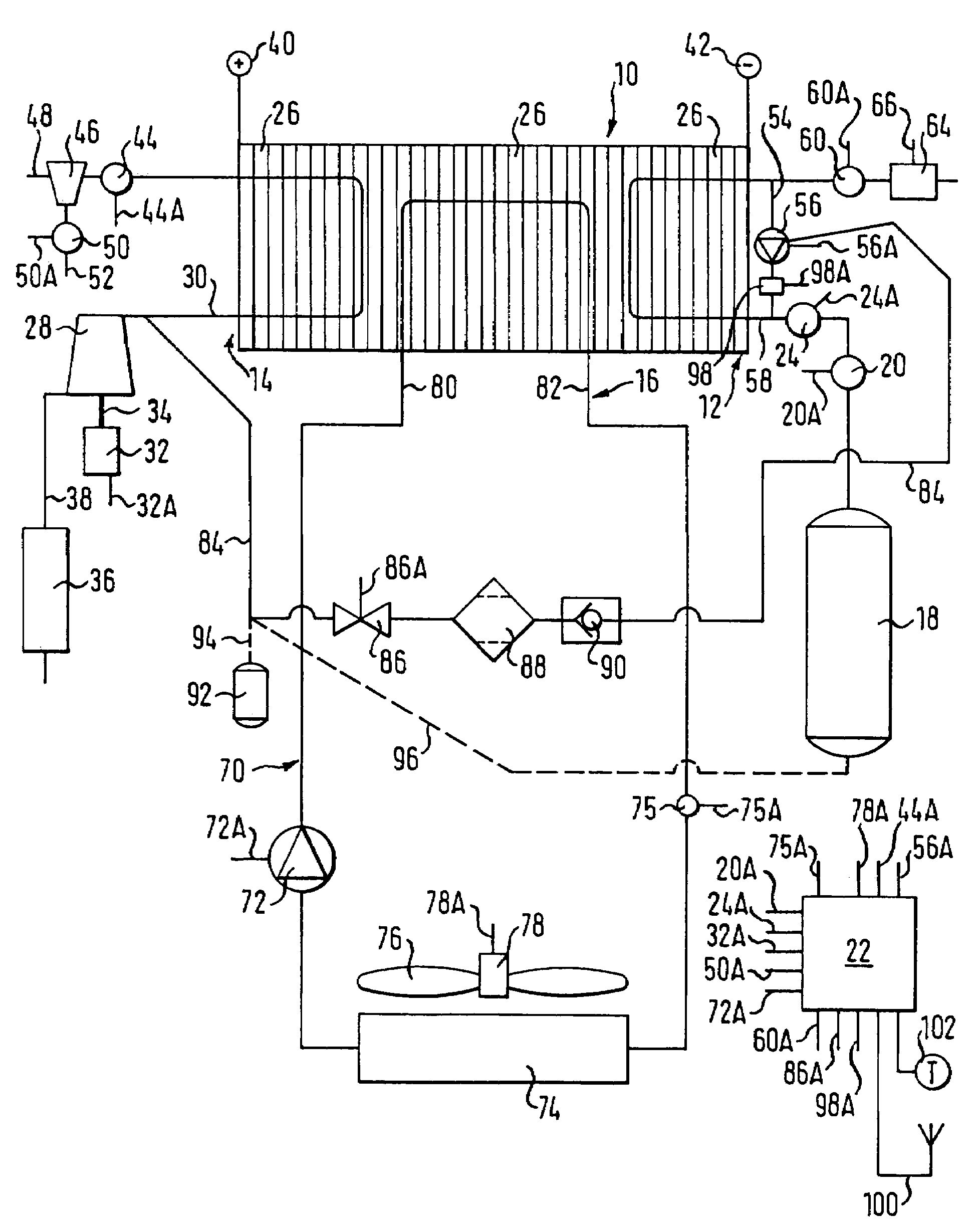
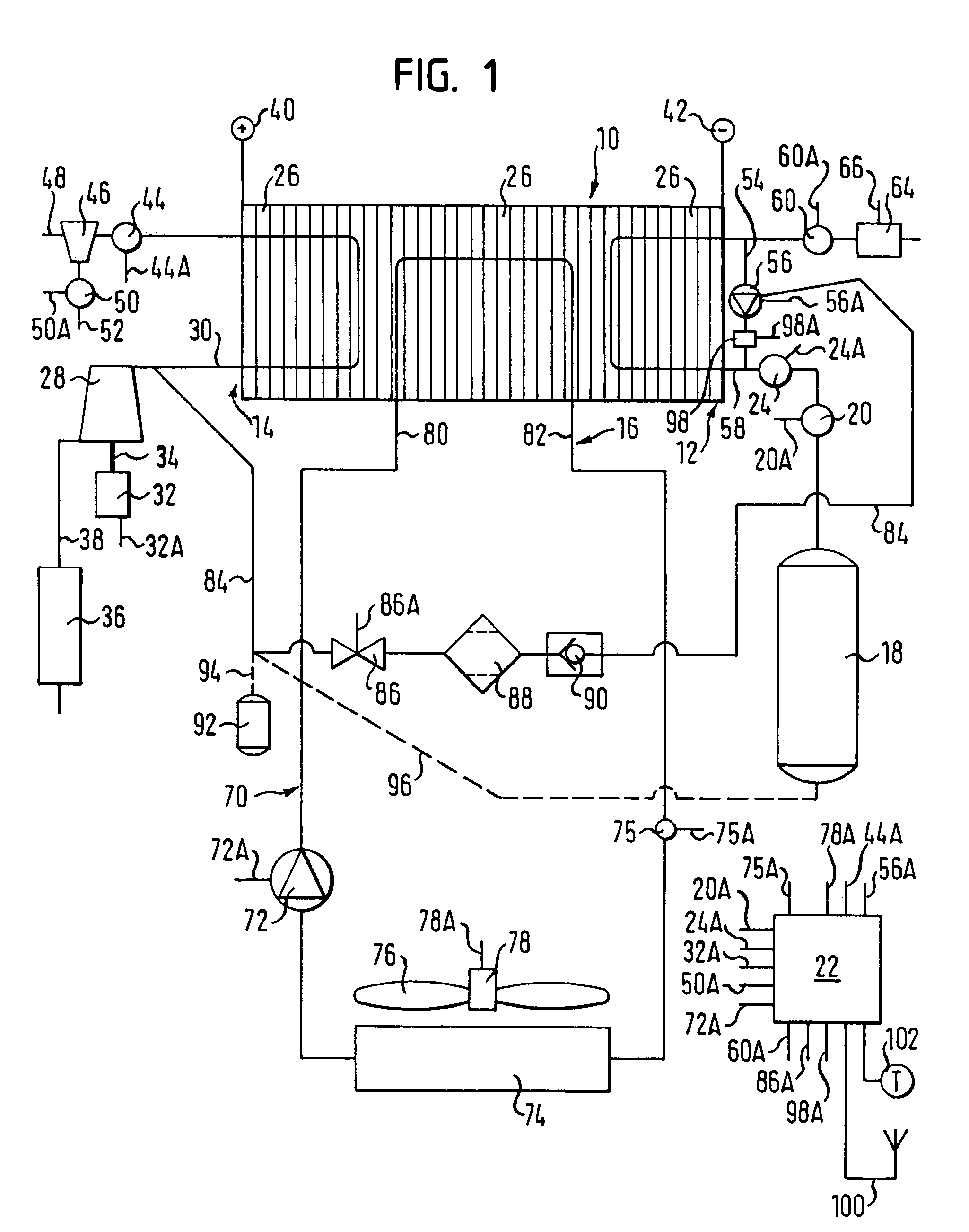
[0031]FIG. 1 shows a schematic representation of a fuel cell system consisting of a fuel cell stack 10 with an anode side 12 and a cathode side 14. The fuel cell system also has a coolant cycle 16 which is filled with an insulating coolant which, depending on where the fuel cell system is operated, does not freeze at the maximally anticipated negative temperatures there, i.e. does not pass into the solid state. Instead of using a coolant in liquid form the fuel cell system can also be provided with air cooling.

[0032]On the anode side 12, a fuel such as hydrogen-rich synthetic gas is stored in a low-temperature storage container 18 or in another suitable pressurized container. The reference number 20 denotes a valve which serves to reduce the pressure in the storage container 18 to a lower feed pressure. The valve 20 is governed by a control unit 22 through conduit 20A. In order to simplify the representation the curve of the control conduit 20A between the valve 20 and the control 2...


PUM

PropertyMeasurementUnit
temperaturesaaaaaaaaaa
temperatureaaaaaaaaaa
timeaaaaaaaaaa

Abstract

The invention pertains to a process for preventing the freezing of water in a structural component containing at least one moving part in the anode cycle of a fuel cell system, characterized by the fact that at the time of a switching-off process the structural component is scavenged by a dry scavenging gas in order to remove a quantity of water present there.

Description

BACKGROUND OF THE INVENTION[0001]The present invention pertains to a process for preventing the freezing of water in a structural component of a fuel cell system, especially in a component containing at least one movable part in the anode cycle of a fuel cell system as well as a fuel cell system with several fuel cells combined to form a fuel cell stack which has an anode side, a cathode side and a membrane arranged between the anode side and the cathode side, the anode sides of the fuel cells being joined together to form an anode cycle and which also includes a device for supplying fresh gaseous fuel, a drain valve which is designed for continuous or discontinuous bleeding off of at least part of the gases flowing in the anode cycle and at least one component having a moving part such as a fuel recirculation pump, the fuel recirculation pump feeding the exhaust gases emerging from the anode sides of the fuel cell and containing useful fuel back to the anode sides of the fuel cells...

Claims


Application Information

Patent Timeline
Patent Type & Authority Patents(United States)
IPC IPC(8): H01M8/00H01M8/04
CPCH01M8/04097H01M8/04179H01M8/04231Y02E60/50F04D23/008F04D17/10F04D29/706
Inventor HOBMEYR, RALPH T. J.WEXEL, DIRK M.
Owner GM GLOBAL TECH OPERATIONS LLC
Why Eureka
Try Eureka