Head-mounted display apparatus for profiling system

a profiling system and display apparatus technology, applied in the direction of measuring devices, scientific instruments, instruments, etc., can solve the problem that the display of data may not be convenient for a non-expert user to appreciate and interpret the displayed data

Inactive Publication Date: 2007-05-31
MICROMENTIS
View PDF55 Cites 18 Cited by
  • Summary
  • Abstract
  • Description
  • Claims
  • Application Information

AI Technical Summary

Benefits of technology

[0016] Another aspect of the invention provides a method for referencing a head-mounted display device in a global reference system. The method comprises: providing three target points disposed in the global reference system and defining a target plane; displaying a first reticle to a first eye and a second reticle to a second eye of the head mounted display device; aligning the first and second reticles from one another; aligning the reticles to a first target point and reading a first position and orientation of the head-mounted display device in a device reference system; aligning the reticles to a second target point and reading a second position and orientation of the head-mounted display device in a device reference system; aligning the reticles to a third target point and reading a third position and orientation of the head-mounted display device in a device reference system; calculating a translation matrix between the global reference system and the device reference system using the first, second and third positions and orientations; and saving the calculated translation matrix in memory.

Problems solved by technology

The displayed data may not be convenient for a non-expert user to appreciate and interpret the displayed data for its practical use of the characterization.

Method used


Image

  • Head-mounted display apparatus for profiling system
  • Head-mounted display apparatus for profiling system
  • Head-mounted display apparatus for profiling system

Examples


Embodiment Construction

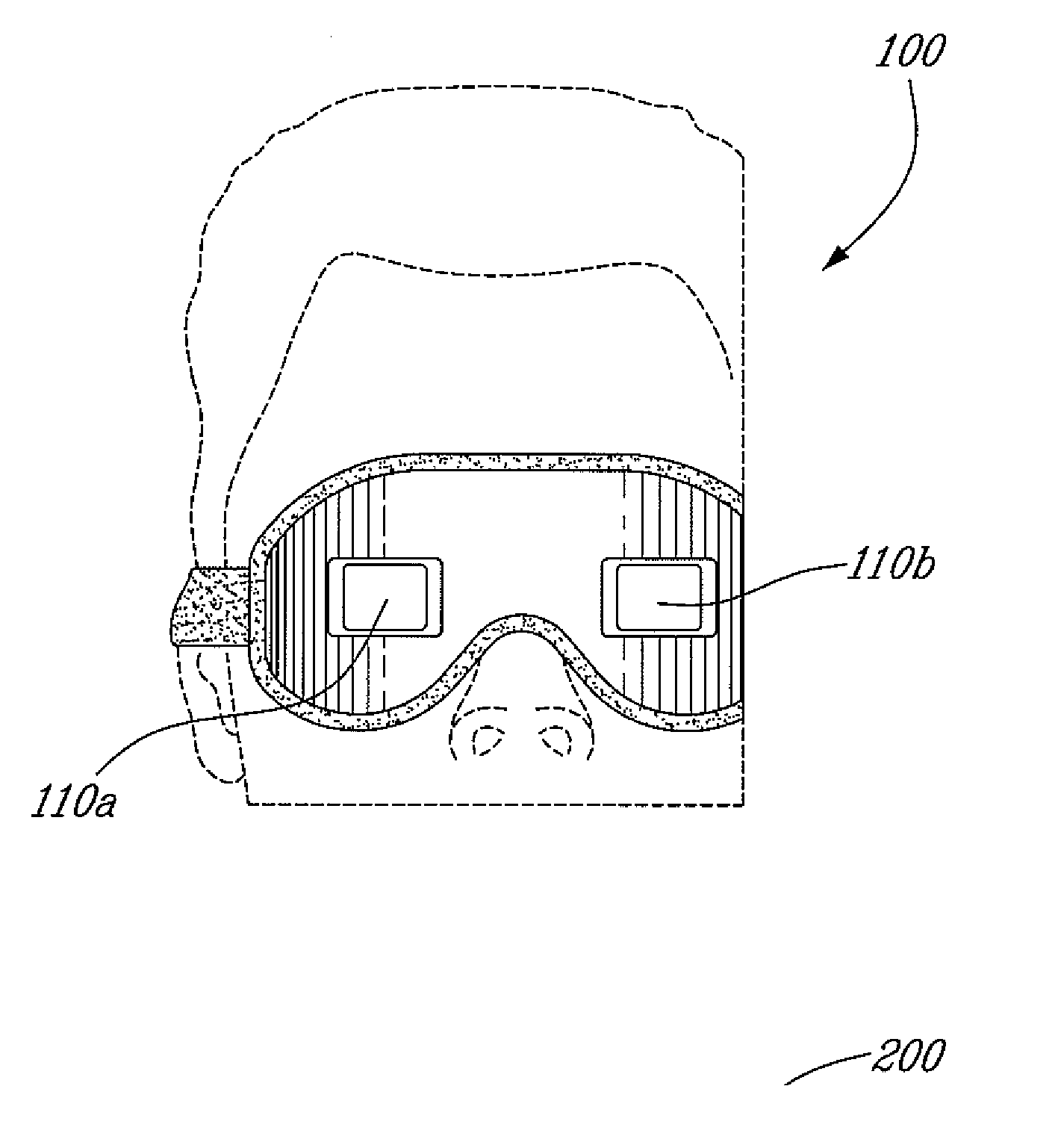
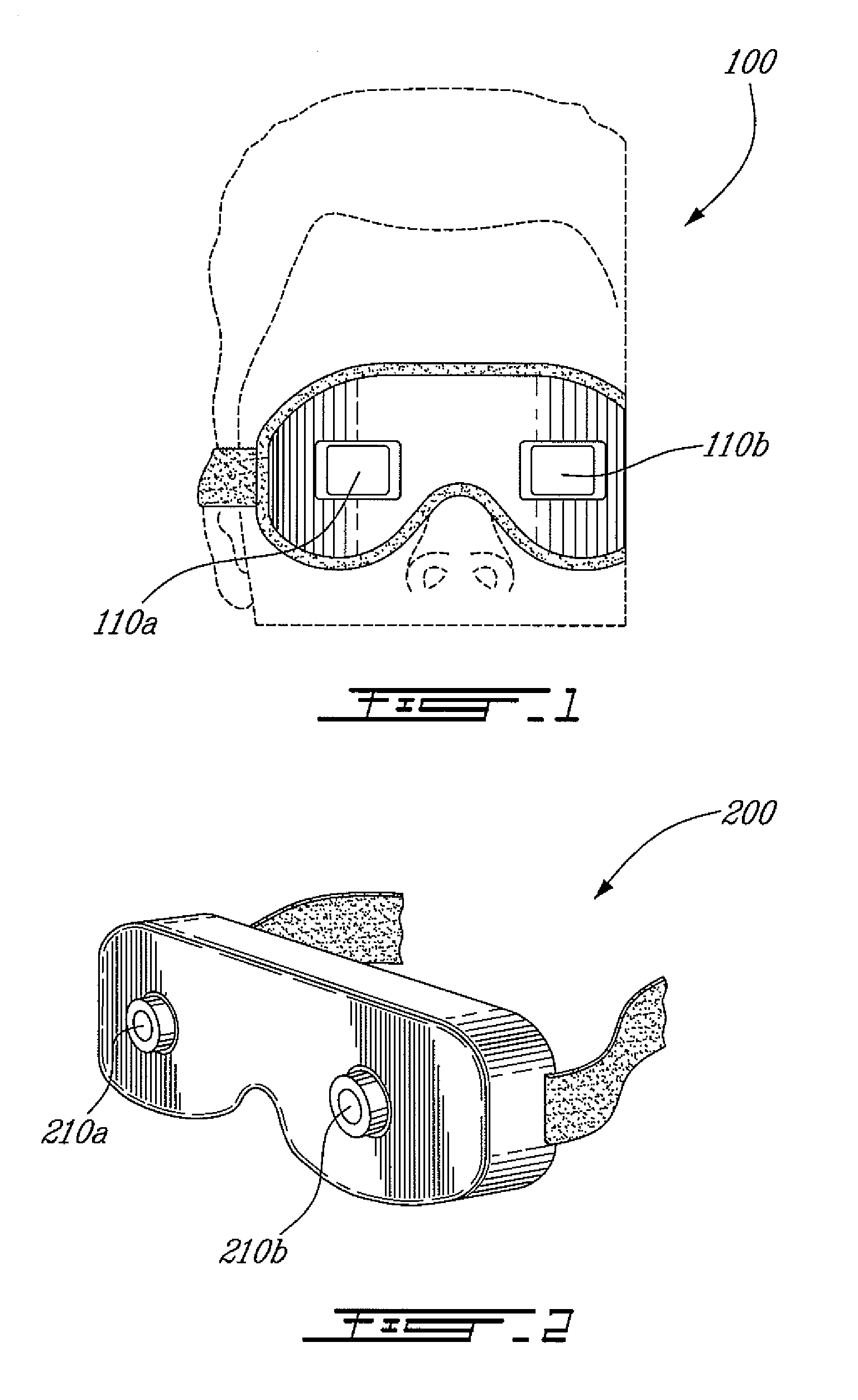
[0027] Now referring to the drawings, FIG. 1 shows an example of a head-mounted display 100 to be used for visualizing a medium through a surface. The head-mounted display 100 is adapted to be worn in front of the eyes of a user and have two see-through screens 110a, 110b that transmits light such that the user can directly see the real environment in front of his / her eyes through the see-through screens 110a, 110b. An image of the medium under the surface is projected on each see-through screen 110a, 110b. The images provided on the right and the left eye corresponds to a graphical representation of a characterization model of the medium in stereoscopy such that the characterization of the medium appears in three-dimensions to the user. The images are updated in real-time as the user moves around the characterized medium such that the user visualizes the characterization of the medium as if he / she could see through the surface. The see-through screens 110a, 110b can use see-through...


PUM


Abstract

The invention provides a head-mounted display to visualize a medium through a surface by displaying an image characterizing the medium under the surface provided by a profiling system and referenced in the real environment of the user. An image of the medium under the surface is projected in front of one or both eyes of a person wearing the head-mounted display, in superimposition with the real environment of the user. The head-mounted display comprises a positioning sensor, such as an inertial positioning sensor, for determining its position and orientation in the real environment. As the user moves around the medium, the image of the medium is updated to display the medium as if it could be seen through the surface. In one embodiment of the invention, the image of the medium under surface is displayed in stereoscopy, the user thereby visualizing the medium in three dimensions.

Description

CROSS-REFERENCE TO RELATED APPLICATIONS [0001] This application is a continuation-in-part, and claims benefit under 35USC§120 of now pending U.S. patent application Ser. No. 11 / 482,113 filed on Jul. 7, 2006, which is a continuation, and claims benefit under 35USC§120 of U.S. patent application Ser. No. 10 / 324,073 filed on Dec. 20, 2002 and issued on Jul. 11, 2006 to U.S. Pat. No. 7,073,405, which claims the benefit of priority under 35USC§119 from Canadian Patent Application no. 2,366,030 filed on Dec. 20, 2001, the specifications of which are incorporated by reference as if set forth in full in this document.BACKGROUND OF THE INVENTION [0002] 1) Field of the Invention [0003] The present invention relates to the field of non-intrusive testing of a medium located under a surface. More specifically, the present invention is concerned with the display of the characterization of a medium under a surface. [0004] 2) Description of the Prior Art [0005] In the field of geophysical explorati...

Claims


Application Information

Patent Timeline
Patent Type & Authority Applications(United States)
IPC IPC(8): G01V1/00
CPCG01V1/16G01V1/22G01V1/34
Inventor RIOUX, DANIEL
Owner MICROMENTIS
Why Eureka
Try Eureka