Array for the illumination of an object

a technology for objects and arrays, applied in lighting and heating apparatus, lasers, projectors, etc., can solve the problems of less performance than achieved, disadvantageously different distances from sources, and series connections that require a greater installation space, so as to achieve better bundling efficiency

Inactive Publication Date: 2005-06-23
CARL ZEISS JENA GMBH
View PDF7 Cites 43 Cited by
  • Summary
  • Abstract
  • Description
  • Claims
  • Application Information

AI Technical Summary

Benefits of technology

[0017] The light from the two-dimensional array of individual emitters, the light component of which limits output, is preferably capable of being bunched through a reflective side of the dichroitic beam splitter. Because it is not nece

Problems solved by technology

A disadvantage of the use of prisms to combine beams is that the dichroitic layers used are embedded in glass and adhesive cement, a jump in the refractive index from glass to air does not occur and, as a result, less performance is achieved than in the case of a jump in the refractive index against air.
Two panels connected in series require greater installation sp

Method used


Image

  • Array for the illumination of an object
  • Array for the illumination of an object
  • Array for the illumination of an object

Examples


Embodiment Construction

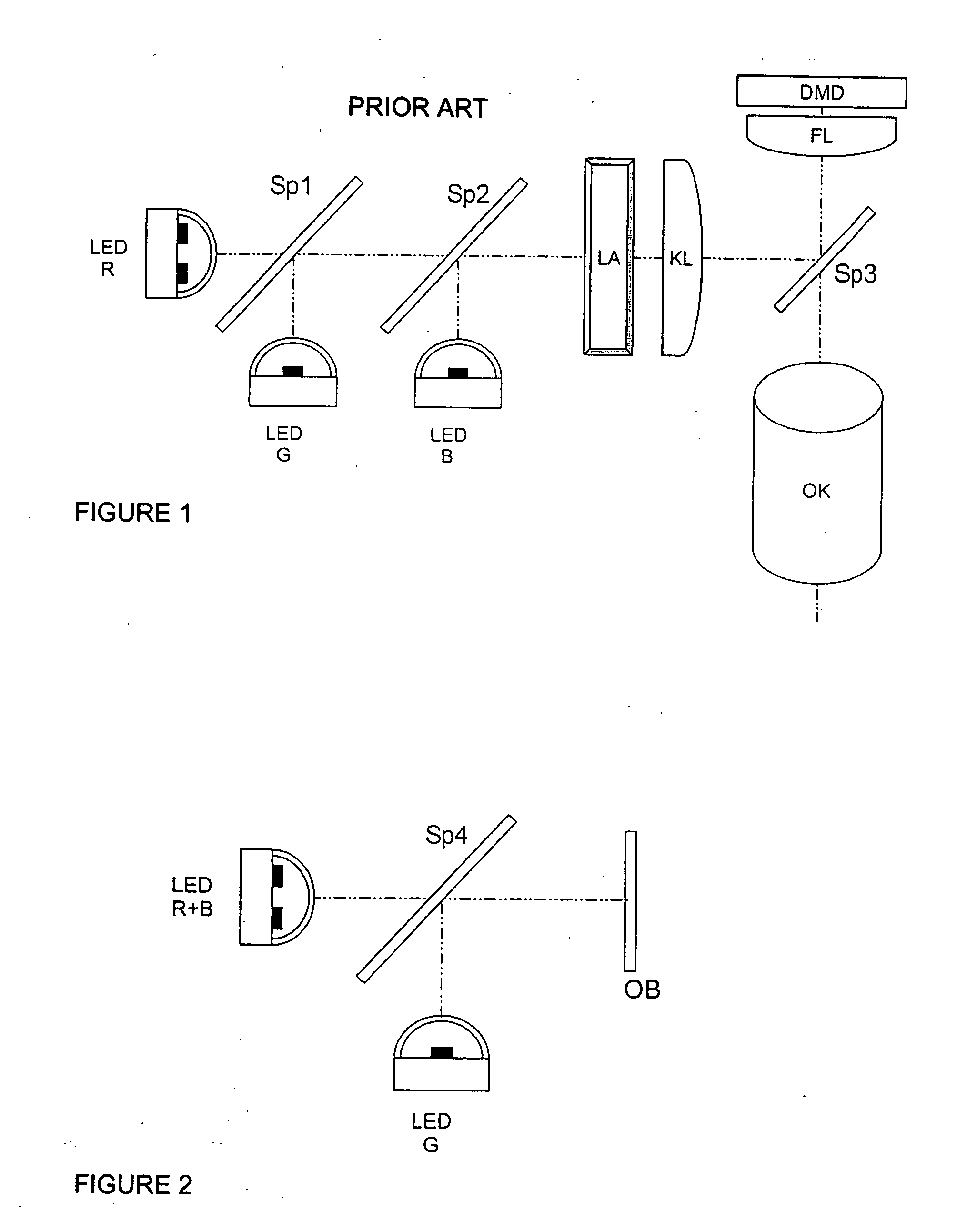
[0030]FIG. 1 shows an array for illumination based on the example of a project having a DMD matrix, as was initially described as the state of the art.

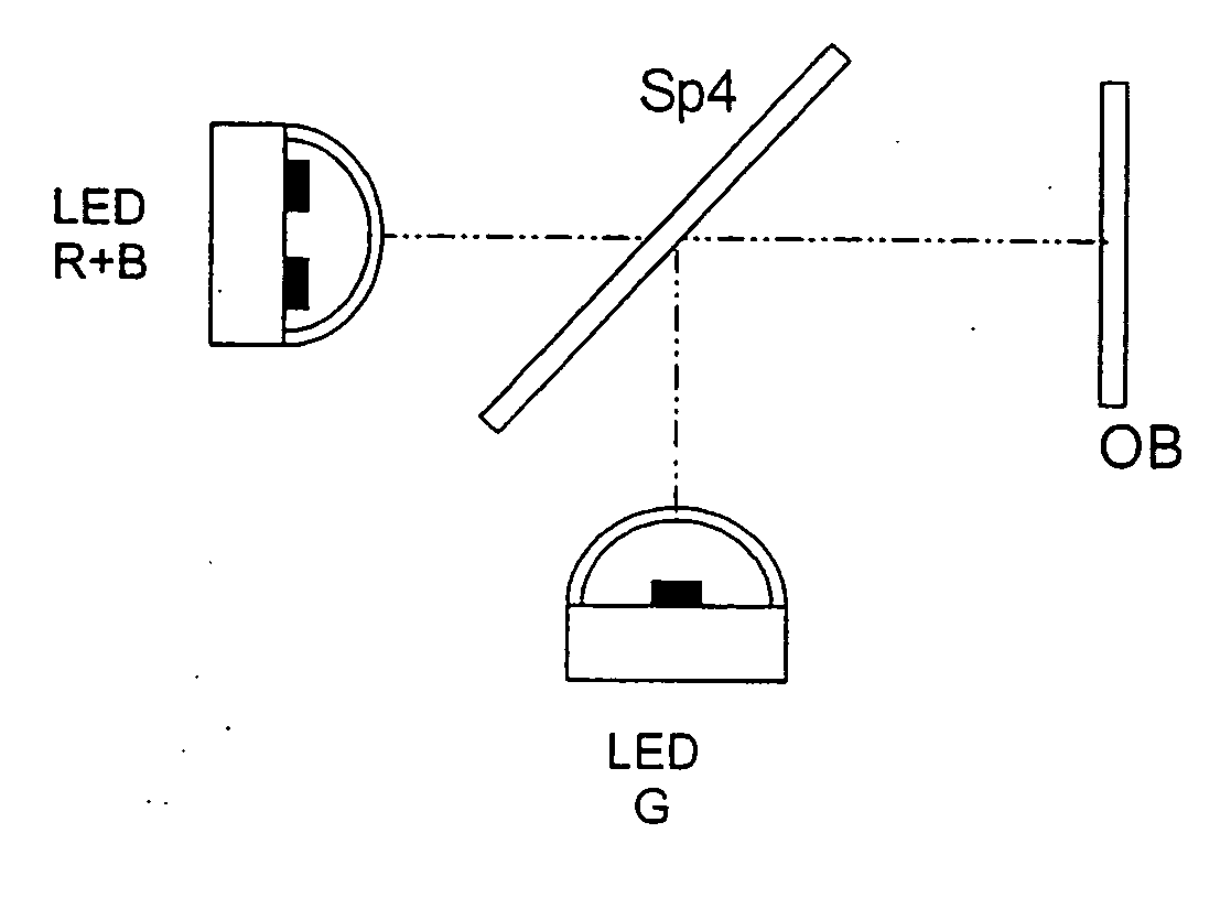
[0031]FIG. 2 shows a two-dimensional array of individual emitters, which, in the example, are divided into two LED modules, LED R+B and LED G, the emitted light components of which are spatially superimposed through a dichroitic beam splitter Sp4. The superimposed light components are used to illuminate an object OB.

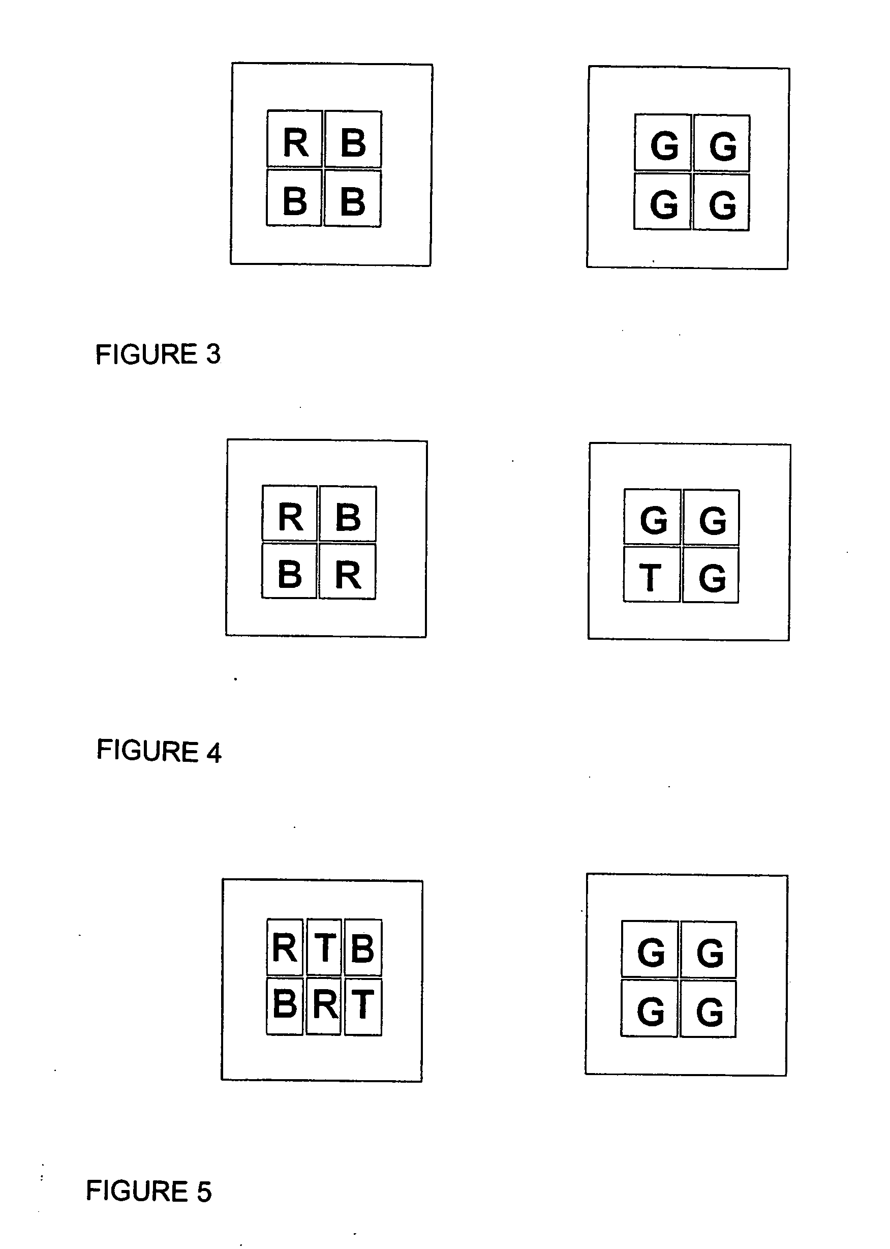
[0032] A first LED module LED R+B contains three individual emitters for the color blue and one individual emitter for the color red. A second LED module LED G contains four individual emitters for the color green (see FIG. 3). An example of the output ratios of currently available LEDs for red: green: blue is 6:1:2. Green is the limiting color channel. While retaining the balanced output performance for generating white light, three blue emitters and one red emitter are used in one module. This results in two LED module...


PUM


Abstract

An array for the illumination of an object, preferably a microdisplay, by means of a two-dimensional array of individual emitters, the focal wavelengths of which correspond, respectively to the primary colors red, green and blue, and an apparatus for the spatial superimposition of the light components. The invention is characterized in that a first two-dimensional array of individual emitters and a second two-dimensional arrays of individual emitters are provided, the light components of which are spatially combined by means of a beam splitter, and the first two-dimensional array of individual emitters transmits two spectral ranges, each having a focal point wavelength, wherein the output components of the at least three light components are dimensioned in such a way that the spatially superimposed light components produce white illumination light.

Description

FIELD OF THE INVENTION [0001] The invention relates to an array for the illumination of an object, preferably a microdisplay, by means of a two-dimensional array of individual emitters, the focal point wavelengths of which correspond, respectively to the primary colors red, green and blue, and an apparatus for the spatial superimposition of the light components. BACKGROUND OF THE INVENTION [0002] An illumination unit which operates with a plurality of two-dimensionally extended light sources (e.g., LEDs) is known from WO99 / 64912 A1 for use in projectors. The light components from three LED arrays, in the colors red, green and blue, are combined by a dichroitic prism and supplied to an LCD display. [0003] A disadvantage of the use of prisms to combine beams is that the dichroitic layers used are embedded in glass and adhesive cement, a jump in the refractive index from glass to air does not occur and, as a result, less performance is achieved than in the case of a jump in the refract...

Claims


Application Information

Patent Timeline
IPC IPC(8): G02B27/10G03B21/14G03B21/20G03B21/28H01L33/00H01S5/00
CPCG03B21/14G03B21/2066G03B33/12
Inventor GEISSLER, ENRICO
Owner CARL ZEISS JENA GMBH
Why Eureka
Try Eureka