Endoscope apparatus and method for controlling fluorescence imaging apparatus

a fluorescence imaging and endoscope technology, applied in the field of endoscopes, can solve problems such as distorted balance and the like of obtained images

Active Publication Date: 2013-04-18
OLYMPUS CORP
View PDF10 Cites 44 Cited by
  • Summary
  • Abstract
  • Description
  • Claims
  • Application Information

AI Technical Summary

Benefits of technology

[0010]An endoscope apparatus according to an aspect of the present invention includes: a light source portion including light sources that irradiate living tissue with an excitation light for generating fluorescence and a reference light for generating a reflected light alternately; an image pickup portion including image pickup devices having a predetermined number of pixels for picking up images of the fluorescence generated by the irradiation of the living tissue with the excitation light and a reflected light of the reference light reflected by the living tissue; a signal processing portion that generates image signals from signals picked up by the image pickup portion; an addition processing portion that generates, from fluorescence signals obtained when the image of the fluorescence is picked up or the image signals of the fluorescence generated by the signal processing portion, addition processed signals of fluorescence in which a plurality of adjacent pixels are added; a light quantity control portion that controls a quantity of at least one of the excitation light and the reference light so as to maintain a predetermined light quantity ratio between quantities of the excitation light and the reference light from the addition processed signals of the fluorescence and reflected light signals as the image signals of the reflected light on the basis of change in a number of pixels to be added in the addition processing; and a superimposition processing portion that outputs, to a display portion, superimposed image signals in which the addition processed signals of the fluorescence and the reflected light signals are superimposed, with the predetermined light quantity ratio being maintained in the light quantity control portion.
[0011]A method for controlling a fluorescence imaging apparatus according to an aspect of the present invention includes: a signal processing step in which a signal processing portion generates image signals from obtained fluorescence signals and reflected light signals reflected by living tissue; a pixel addition processing step in which a pixel addition processing portion generates addition processed signals of fluorescence obtained by addition processing among a plurality of adjacent pixels from the fluorescence signals or the image signals of the fluorescence generated in the signal processing step; a light adjusting signal generating step in which, a light adjusting signal generating portion generates a light adjusting signal for controlling a quantity of at least one of the excitation light and the reference light by a light quantity control portion so as to maintain a predetermined light quantity ratio between quantities of the excitation light and the reference light from the addition processed signals of the fluorescence and reflected light signals as the image signals of the reflected light on the basis of change in the number of pixels to be added in the pixel addition processing step; and a superimposition signal generating step in which a superimposition processing portion generates superimposed image signals in which the addition processed signals of the fluorescence and the reflected light signals are superimposed, with the predetermined light quantity ratio being maintained in the light adjusting signal generating step.

Problems solved by technology

However, disadvantageously, in the case where an image is obtained or generated by means of illumination by a plurality of light-emitting devices, or a plurality of images are displayed superimposed on one another, if a light quantity ratio of the plurality of light-emitting devices is not controlled to be constant, the balance and the like of an obtained image may be distorted.

Method used


Image

  • Endoscope apparatus and method for controlling fluorescence imaging apparatus
  • Endoscope apparatus and method for controlling fluorescence imaging apparatus
  • Endoscope apparatus and method for controlling fluorescence imaging apparatus

Examples


first embodiment

Modification of First Embodiment

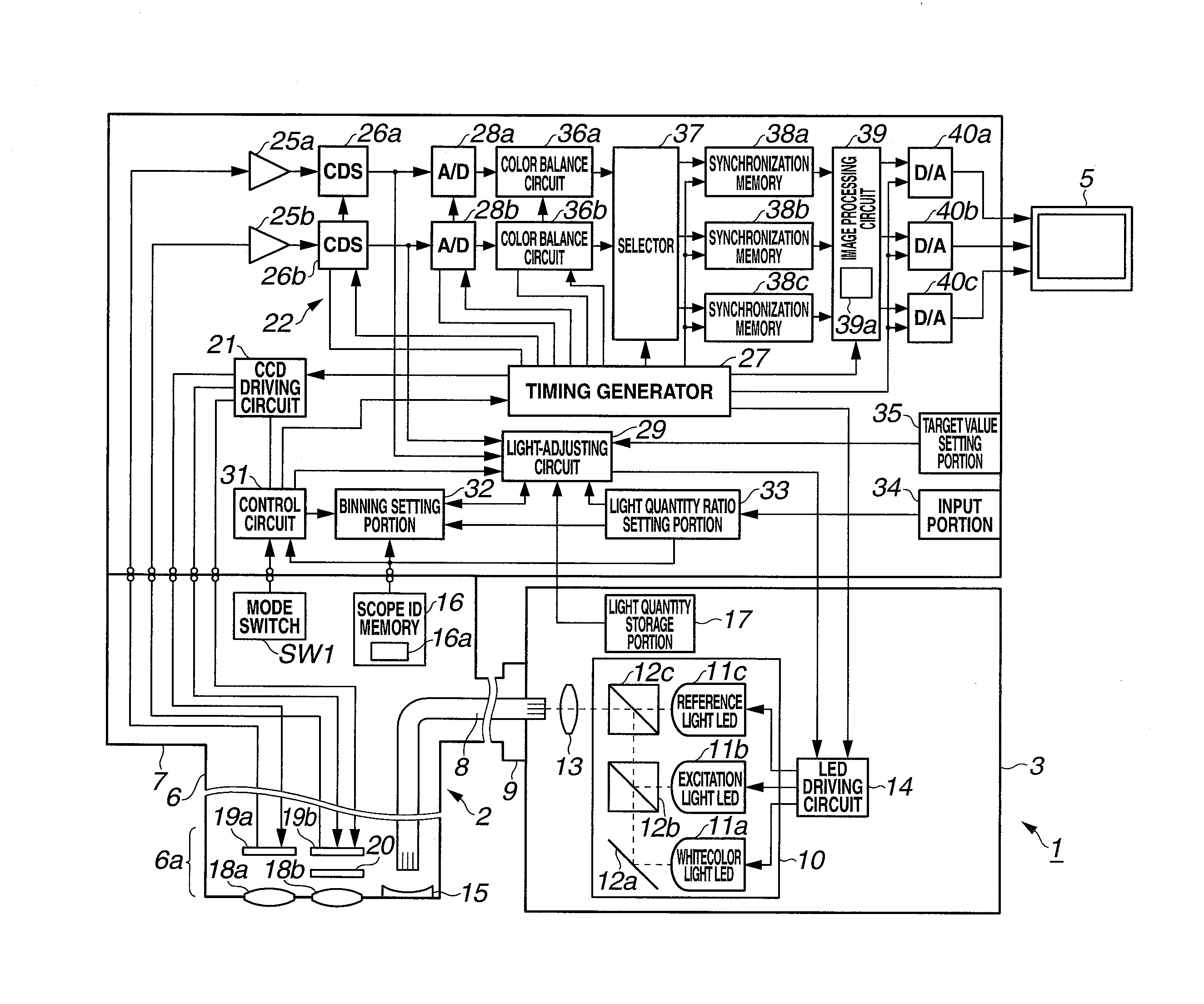
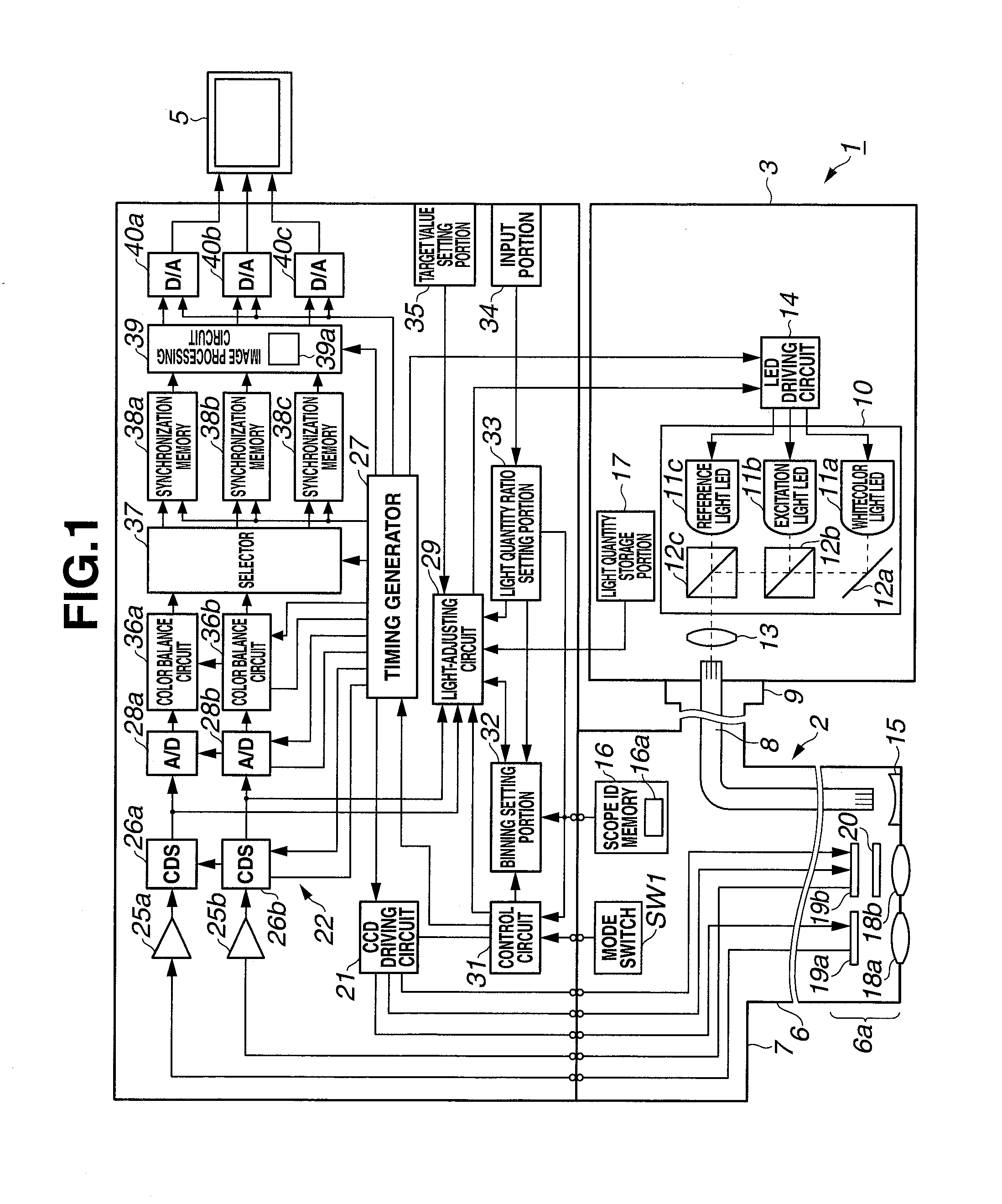
[0135]FIG. 10 shows an endoscope apparatus 1B of a modification of the first embodiment. The endoscope apparatus 1B has a configuration in which the light quantity storage portion 17 is removed from and a light quantity measurement portion 55 is provided in the endoscope apparatus 1 in FIG. 1.

[0136]The light quantity measurement portion 55 measures the quantity of an excitation light from the excitation light LED 11b and the quantity of a reference light from the reference light LED 11c, from light transmitted through a fiber 56 that receives part of light supplied from, for example, the condenser lens 13 to an incident end face of the light guide 8.

[0137]The quantity of the excitation light and the quantity of the reference light by the reference light LED 11c which are measured by the light quantity measurement portion 55 are inputted to the light-adjusting circuit 29. The light-adjusting circuit 29 refers to the quantities of the excitation light a...

second embodiment

[0144]Next, a second embodiment of the present invention will be described. The present embodiment has a configuration in which for example, the image processing circuit 39 in FIG. 1 or FIG. 10 provides therein an image addition circuit 39b that adds about two to four frames of images adjacent on a time-series basis for only fluorescence image components.

[0145]FIG. 11 shows the image processing circuit 39 in the present embodiment. As shown in FIG. 11, fluorescence image signals are inputted to the image addition processing circuit 39b. The image addition processing circuit 39b outputs, to the superimposition processing portion 39a, image addition processed signals in which images of a plurality of frames adjacent on a time-series basis are added.

[0146]A superimposition processing circuit 61 of the superimposition processing portion 39a also receives image signals of a reflected light (as input). The superimposition processing circuit 61 generates image signals of a composite image ...


PUM


Abstract

An endoscope apparatus includes: a light source portion that irradiates an excitation light and a reference light alternately; an image pickup portion that picks up images of the fluorescence from the living tissue and the reflected light; a signal processing portion that generates image signals from picked up signals; an addition processing portion that generates, from image signals of fluorescence, addition processed signals of fluorescence in which pixels are added; a light quantity control portion that controls the quantity of light so as to maintain a predetermined light quantity ratio between the quantities of the excitation light and the reference light from the addition processed signals of fluorescence and image signals of the reflected light; and a superimposition processing portion that superimposes the addition processed signals and the image signals of the reflected light, with the predetermined light quantity ratio being maintained.

Description

CROSS REFERENCE TO RELATED APPLICATION[0001]This application is a continuation application of PCT / JP2012 / 058968 filed on Apr. 2, 2012 and claims benefit of Japanese Application No. 2011-127566 filed in Japan on Jun. 7, 2011, the entire contents of which are incorporated herein by this reference.BACKGROUND OF THE INVENTION[0002]1. Field of the Invention[0003]The present invention relates to an endoscope apparatus that performs fluorescence imaging and a method for controlling a fluorescence imaging apparatus.[0004]2. Description of the Related Art[0005]An endoscope apparatus which uses an endoscope has been widely used in a medical field. A light source apparatus of a conventional endoscope has generally adopted a scheme to attain the irradiation with a desired light from a white color light source such as a xenon lamp and a halogen lamp through a band-pass filter.[0006]In recent years, inexpensive and high-output solid light-emitting devices such as a light emitting diode (abbreviat...

Claims


Application Information

Patent Timeline
Patent Type & Authority Applications(United States)
IPC IPC(8): A61B1/04A61B1/00A61B1/06
CPCG02B23/2461G02B2207/113A61B1/00006A61B1/00009A61B1/0005A61B1/043G01N2021/6484A61B1/0661H04N5/2354H04N5/2356H04N2005/2255G01N21/6456A61B1/063A61B1/000095A61B1/0655H04N23/555H04N23/743H04N23/74
Inventor TAKEI, SHUNJIDOGUCHI, NOBUYUKI
Owner OLYMPUS CORP
Why Eureka
Try Eureka