Moving picture encoding method and moving picture decoding method

a technology of moving picture and encoding method, which is applied in the field of moving picture encoding method and moving picture decoding method, can solve the problems of film grain damage to a unique video quality, large amount of data, and limited capacity, so as to improve the picture quality of the coded stream and improve the reproducibility

Inactive Publication Date: 2006-11-16
PANASONIC CORP
View PDF0 Cites 43 Cited by
  • Summary
  • Abstract
  • Description
  • Claims
  • Application Information

AI Technical Summary

Benefits of technology

[0031] As clear from the above-mentioned description, with the moving picture coding method and a moving picture decoding method in the present invention, it becomes possible to improve the reproducibility by recovering the high-definition components even in the case where the inputted pictures are coded in a low bit rate. Also, it becomes possible to improve the picture quality of the coded stream that has been sent in a low bit rate later.

Problems solved by technology

When sending and recording moving pictures, a large amount of data must be sent via a conventional communication channel whose frequency band is limited, and such data must be stored in a conventional storage medium whose capacity is limited.
In the case of performing coding using a lowered bit rate in the motion picture compression like this, film grains are removed, resulting in causing a problem that such film grains damage a unique video quality.
The drawback of this method is that film grain information must be standardized according to a known statistical film grain model in order to obtain respective parameters.
A conventional film grain removing method like this requires high-level calculation and complicated hardware especially because of motion compensation filtering.
However, in the moving picture coding method and the moving picture decoding method, white noises are added uniformly according to the flag indicating the noise amount that have been removed using a pre-filter, and the methods entail a problem that the reproducibility of pictures is made low.
Also, in the case of coding fine pictures that have parts where a lot of high-frequency components are used, for example, parts of green trees, in a lowered bit rate, such high-frequency components are removed together with such film grains, and the methods entail a problem that fine parts cannot be reproduced.

Method used


Image

  • Moving picture encoding method and moving picture decoding method
  • Moving picture encoding method and moving picture decoding method
  • Moving picture encoding method and moving picture decoding method

Examples


first embodiment

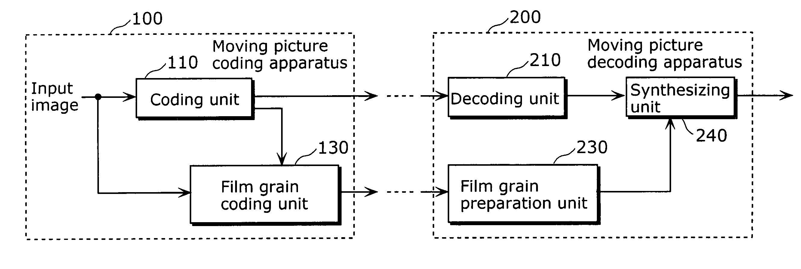
[0068]FIG. 3 is a block diagram showing the overall configuration of the moving picture coding apparatus and the moving picture decoding apparatus that use the moving picture coding method and the moving picture decoding method in a first embodiment of the present invention.

[0069] The moving picture coding apparatus 100 is for coding film grains separately from main pictures, and includes a coding unit 110 and a film grain coding unit 130 as shown in FIG. 3. On the other hand, the moving picture decoding apparatus 200 is for superimposing such film grains on decoded pictures, and includes a decoding unit 210, a film grain preparation unit 230 and a synthesizing unit 240 as shown in FIG. 3.

[0070] First, the moving picture coding apparatus 100 will be described.

[0071]FIG. 4 is a block diagram showing the structure of the coding unit 110 of the moving picture coding apparatus 100.

[0072] The coding unit 110 includes a control unit 111, a prediction residual coding unit 112, a variab...

second embodiment

[0130] This embodiment will describe the case where only a part of macro blocks, among the pictures to be coded, are coded with high quality instead of coding representative patterns separately.

[0131]FIG. 18 is a block diagram showing the structure of the coding unit 140 and the film grain coding unit 150 of the moving picture coding apparatus in the second embodiment of the present invention. Note that the same parts as the ones in the first embodiment are assigned the same reference numbers, and the descriptions of them will be omitted.

[0132] This embodiment differs from the first embodiment in the operations performed by (a) the control unit 141 of the coding unit 140, and (b) the selection unit 151 of the film grain coding unit 150 and the variable length coding unit 152.

[0133] The selection unit 151 of the film grain coding unit 150 notifies the variable length coding unit 152 and the control unit 141 of the coding unit 140, of the position information of the macro block sel...

third embodiment

[0141] The above-described first and second embodiments have described film grain components, but this embodiment will describe the case of processing high-definition components included in fine images and the like having parts where a lot of high-frequency components are included. Since such film grain components are high-definition components, the same method is applicable for the high-frequency components except the film grain components.

[0142]FIG. 22 is a block diagram showing the overall configuration of a moving picture coding apparatus and a moving picture decoding apparatus that use the moving picture coding method and the moving picture decoding method in a third embodiment of the present invention.

[0143] The moving picture coding apparatus 300 is for coding high-definition components separately from the main images, and includes a coding unit 310 and a high-definition coding unit 330 as shown in FIG. 22. On the other hand, the moving picture decoding apparatus 400 is for...


PUM


Abstract

A moving picture coding apparatus (100) includes a coding unit (110) that generates a coded stream by coding inputted pictures and a film grain coding unit (130) that codes a representative pattern by selecting film grain components equivalent to at least one macro block and regarding the film grains as a representative pattern. On the other hand, a moving picture decoding apparatus (200) includes a decoding unit (210) that generates decoded picture data by decoding the coded stream and a film grain preparation unit (230) that prepares a superimposition pattern based on the representative pattern and additional information, and a synthesizing unit (240) that synthesizes the decoded picture data with the superimposition pattern.

Description

TECHNICAL FIELD [0001] The present invention relates to a moving picture coding method for coding pictures constituting a moving picture on a block-by-block basis and a moving picture decoding method for decoding the coded stream. BACKGROUND ART [0002] Film moving picture is made of silver halide crystals that are dispersed in photographic emulsion of the film. The respective pictures that are stored in such a photographic film are generated by exposing and developing the silver halide crystals. In the case of color moving pictures, silver is chemically removed after the development. However, the structure of a silver crystal remains as small grains of dye even after the development. Since, silver crystals are formed randomly in emulsion, the grains are formed randomly and dispersed in the respective pictures. Such a recognizable grain structure is called film grain, and FIG. 1 shows an example of such a grain structure. [0003] A viewer of a moving picture that is being reproduced c...

Claims


Application Information

Patent Timeline
Patent Type & Authority Applications(United States)
IPC IPC(8): H04N11/04H04B1/66H04N7/12H04N11/02G06T5/00H04N7/26H04N7/30H04N7/32H04N7/50
CPCG06T2207/20204H04N19/50H04N19/46H04N19/61G06T5/002H04N19/186H04N19/80H04N19/85H04N19/60
Inventor SCHLOCKERMANN, MARTINWEDI, THOMASWITTMANN, STEFFENKADONO, SHINYAKONDO, SATOSHISASAI, HISAO
Owner PANASONIC CORP
Why Eureka
Try Eureka