Audio signal output control device that suppresses pop sound

a control device and audio signal technology, applied in the direction of gain control, electrical transducers, transducer casings/cabinets/supports, etc., can solve the problems of affecting the affecting the sound quality of the audio signal, and affecting the user's experience, so as to achieve smooth fluctuations

Active Publication Date: 2007-05-31
PANASONIC SEMICON SOLUTIONS CO LTD
View PDF7 Cites 10 Cited by
  • Summary
  • Abstract
  • Description
  • Claims
  • Application Information

AI Technical Summary

Benefits of technology

[0009] In general, in order to prevent the occurrence of a pop sound, it is possible to insert a mute circuit for forcibly blocking or grounding the path of the audio signal until the output of the amplifier etc. reaches a stable steady-state. It is also possible to apply the technology described in the aforementioned patent document 1. Patent document 1 discloses a digital audio amplifier circuit for preventing a pop sound by electrically charging an output capacitor disposed between an amplifier etc. and a speaker with use of PWM (Pulse Width Modulation) waveform duties modulated from audio data, and by including fixed resistors disposed between the output and the power supply line and between the output and the ground so as to be connected only when the power is activated by a switch, thereby gradually changing the current flowing into the smoothing capacitor and smoothly changing the potential of the signal output to the speaker.
[0025] When the digital values are divided unevenly, adjusting the timing according to which the post-division digital values are output to the PWM circuit such that pulses with the same duty ratio are output successively as least often as possible enables the smoothing of fluctuations in the potential of the smoothing capacitor in the count cycle.

Problems solved by technology

This type of pop sound differs in nature from the audio signals to be played back, and can be unpleasant to a user.
Also, if the volume is too high, the pop sound may damage the speaker or create quality issues.
Since the pop sound prevention according to patent document 1 requires that fixed resistors and a mute circuit composed of analog devices be disposed around the output capacitor, the control apparatus cannot be constituted from logic elements, and it is difficult to integrate the control apparatus with the PWM circuit to perform large-scale integration.
The pop sound prevention of patent document 1 is therefore not a sensible countermeasure for pop sounds.

Method used


Image

  • Audio signal output control device that suppresses pop sound
  • Audio signal output control device that suppresses pop sound
  • Audio signal output control device that suppresses pop sound

Examples


embodiment 1

[0038] Structure

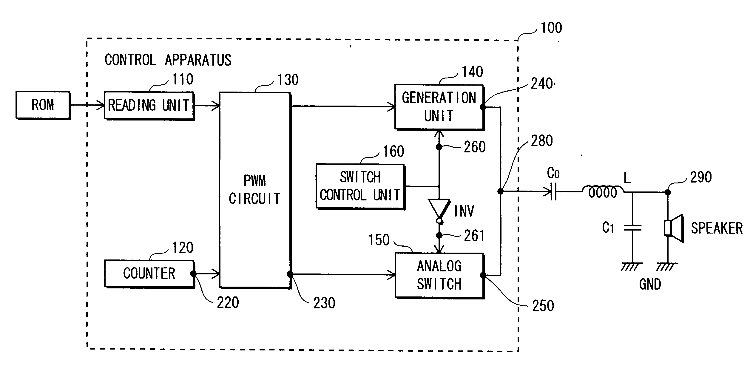
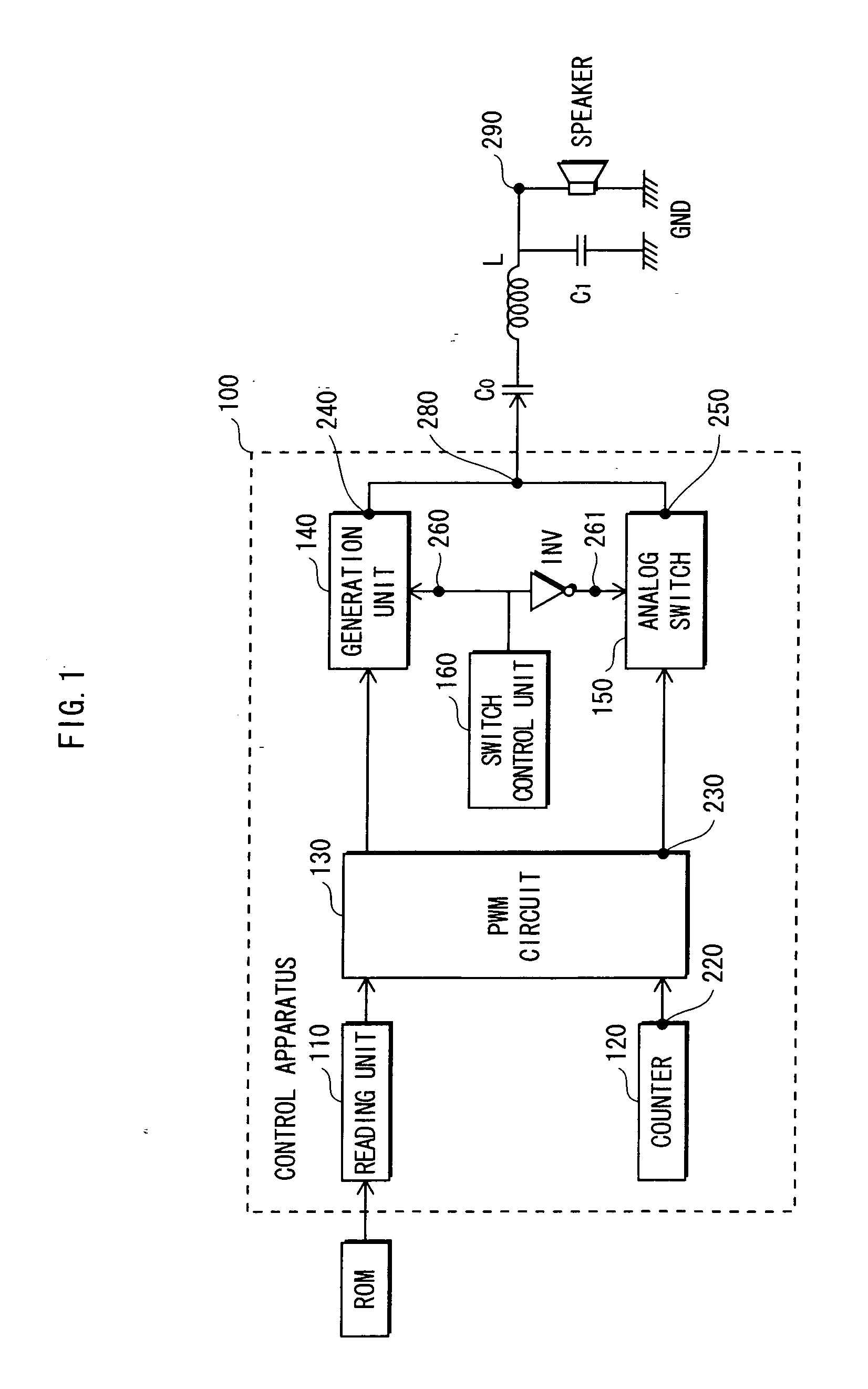
[0039]FIG. 1 shows a structure of a “talking appliance” and a control apparatus 100 in embodiment 1 of the present invention. The “talking appliance” in FIG. 1 has a structure in which audio data stored on a ROM is output as an audio signal by the control apparatus 100 corresponding to the portion enclosed in the dashed line, after which the audio signal passes through a smoothing capacitor C0 for performing smoothing and a noise filter composed of a coil L and a capacitor C1, and is output as audio from the speaker.

[0040] The control apparatus 100 in FIG. 1 includes a reading unit 110, a counter 120, a PWM circuit 130, a generation unit 140, an analog switch 150, and a switch control unit 160.

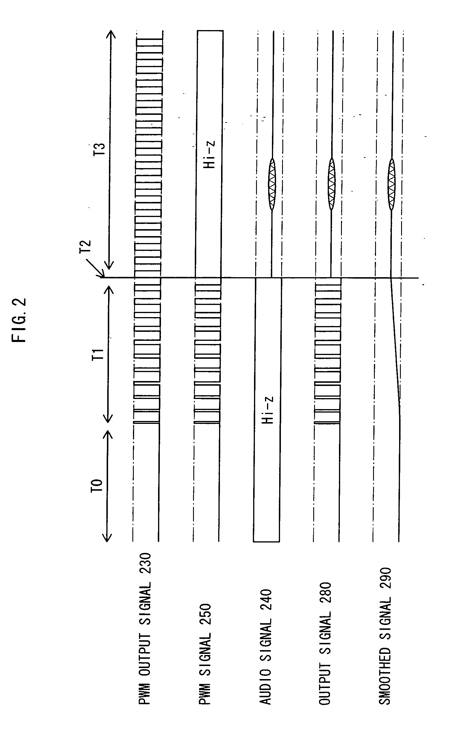
[0041]FIG. 2 shows the condition of the signal at points in FIG. 1 until the potential of the smoothing capacitor C0 when the power is activated enters the steady-state, and audio is played back. In FIG. 2, the time-area of the signals is divided into three periods, which ar...

embodiment 2

[0068] In the control apparatus of embodiment 1, it is necessary for the duty ratios to be set with a high degree of accuracy in order to smoothly raise the output signal 280 from ground level to the reference potential using the PWM output signal 230. To this end, it is necessary to have a large number of reference clock cycles included in one cycle of the PWM output signal 230. Since the reference clock of the PWM circuit 130 cannot be changed easily, increasing the number of reference clock cycles requires the cycle of the PWM output signal 230 to be made longer. However, the potential of the PWM signal rises and falls with each pulse, thereby causing fluctuations in a signal synchronized with the PWM cycle. Noise is generated when the cycle of the PWM output signal 230 is lengthened and the frequency of the fluctuations enters the audible range.

[0069] Therefore, in embodiment 2 of the present invention, each pulse of the PWM output signal 230 is divided into two or more pulses ...


PUM


Abstract

The potential of a smoothing capacitor for a speaker is smoothly changed by controlling the potential with use of a PWM signal and switching between outputting the PWM signal and an actual audio signal, thereby suppressing a pop sound. The scale of circuitry is reduced and cost is lowered by implementing a PWM circuit in a one-chip microcontroller. Noise is eliminated by outputting a pulse that has been divided in the PWM signal generation stage.

Description

BACKGROUND OF INVENTION [0001] 1. Field of the Invention [0002] The present invention relates to technology for controlling the output of an audio signal. [0003] 2. Related Art [0004] In recent years, the development of “talking appliances” has been underway in the home appliance industry, and the aforementioned technology for controlling the output of an audio signal plays an important role in the development of such products. A “talking appliance” refers to a household electronic device that has the functions of announcing operational content by audio and responding to user operations by audio. Technology for controlling the output of an audio signal refers to technology for converting audio data prestored in ROM (Read Only Memory) to analog signals, and outputting the analog signals to a speaker. A conventional control apparatus is structured as a large-scale integrated one-chip microcontroller, and is generally implemented in the aforementioned household electronic devices along...

Claims


Application Information

Patent Timeline
Patent Type & Authority Applications(United States)
IPC IPC(8): H04B15/00H02B1/00
CPCH03F1/305H03F3/217H03F2200/03H03F2200/351H03F2200/417H03G3/301H04R3/007
Inventor ADACHI, KAZUKISUGIOKA, TETSUROKIMURA, KIYOMI
Owner PANASONIC SEMICON SOLUTIONS CO LTD
Why Eureka
Try Eureka