Battery venting system

a battery and venting technology, applied in the direction of secondary cell servicing/maintenance, cell components, grouping of flat cells, etc., can solve the problems of reducing the cell capacity, reducing the service life of the cell, so as to achieve the effect of further enhancing the venting

Inactive Publication Date: 2007-05-31
EASTWAY FAIR
View PDF99 Cites 29 Cited by
  • Summary
  • Abstract
  • Description
  • Claims
  • Application Information

AI Technical Summary

Benefits of technology

[0010] In yet another aspect of the present invention, a carrier of a plurality of battery cells is provided to arrange and hold the plurality of battery cells to define a cell pack. The carrier may be used with battery cells without an outer case, with battery cells having an outer case, or with battery cells having electrically non-conductive sleeves according to the present invention. In one embodiment, the carrier causes the terminals on each end of the cells to be positioned in a substantially same plane.
[0013] According to the present invention, a plurality of battery cells are held between the pair of upper and lower carriers and heat generated from the cells can be dissipated via the elongated fluid flow path. Since the outward-directed peripheral side faces of the battery cells may be free of electrically insulating material and are exposed to the exterior between the pair of upper and lower carriers, heat can also be dissipated from the peripheral side faces of each battery cell. Alternatively, if a sleeve according to the present invention is provided, i.e., with a plurality of apertures, a substantial portion the peripheral side faces of the battery cells will be exposed to the exterior between the pair of upper and lower carriers so that heat can be dissipated from the peripheral side faces of each battery cell.
[0014] The venting effect can be further enhanced by forcing a fluid such as air past and through the cell pack. For example, in another aspect of the present invention, a charger is provided with a fan to force a fluid into the cell pack where it can pass through adjacent cells. Advantageously, the charger may be configured to provide charging of more than a single cell pack, either sequentially or simultaneously. The charger is provided with a mechanism to simultaneously force fluid into two separate cell, while charging.

Problems solved by technology

A disadvantage to providing an electrically insulating case around each cell is that when a plurality of cells are provided to form a cell pack, heat generated upon discharge and upon recharging operations is not easily dissipated.
When the temperature of the cell is raised as a result of the heat generation, self-discharge may reduce the cell capacity or shorten the service life of the cell.
Although this solution may be useful, the plates take up space within the battery pack housing and by virtue of their size still hinder heat dissipation.

Method used


Image

  • Battery venting system
  • Battery venting system
  • Battery venting system

Examples


Embodiment Construction

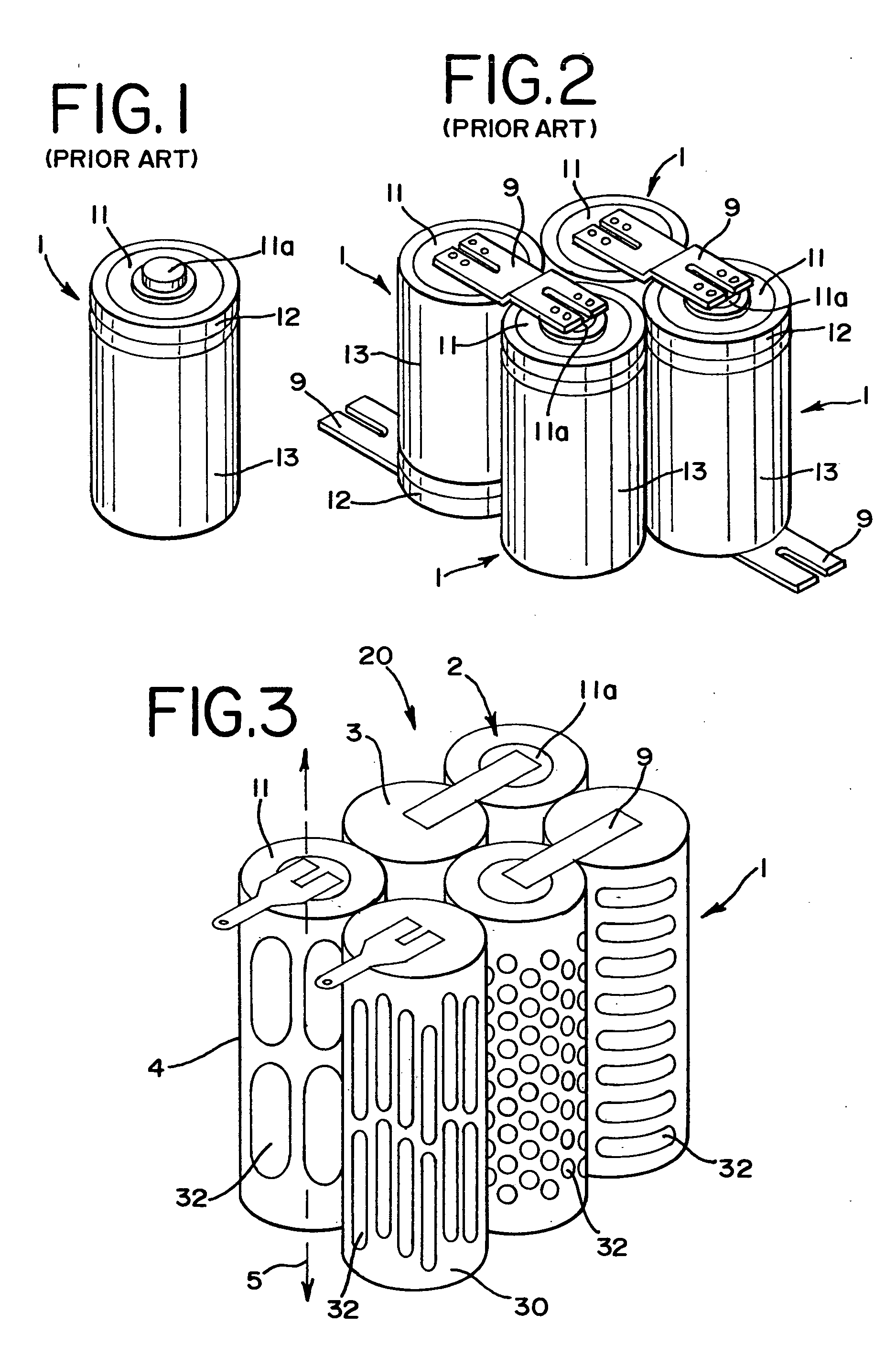
[0028] Referring now to the drawings and initially to FIG. 1, a prior art battery cell is shown. The prior art battery cell 1 has a cylindrical case that contains the cell materials in a closed fashion by a cover 11. A conductive projection 11a is formed in the cover 11, and a safety valve for releasing gasses is disposed in the projection 11a. Generally, the cover 11 having the projection 11a is the positive electrode and the case 12 is the negative electrode. Generally, an outer sleeve 13 is formed from an electrically insulating material so that when the battery cells are intentionally or unintentionally touching each other at the peripheral side face, the battery cells will not discharge.

[0029] When the prior art cylindrical cell 1 is to be used as a power source for an apparatus, generally, a plurality of cells are connected to each other to form a cell pack, as shown in FIG. 2. Two adjacent cells 1 are bridged by an electrically conductive plate 9, such as a nickel plate. The...


PUM

PropertyMeasurementUnit
thicknessaaaaaaaaaa
thicknessaaaaaaaaaa
thicknessaaaaaaaaaa

Abstract

A battery venting system that is useful for cordless power tools. The system can include a cell that may have a sleeve with a plurality of apertures surrounding a peripheral side face of the cell to enhance heat dissipation from the cell. A plurality of cells may be electrically connected to form a cell pack. A carrier includes an upper carrier and a lower carrier to sandwich a plurality of cells that are aligned parallel to each other. The carriers include at least one vent hole that are aligned with a gap formed from adjacent cells to define an elongated fluid flow path. A charger may be provided to receive a housing containing the carrier and may be provided with a fan to direct a flow into the fluid flow path.

Description

BACKGROUND OF THE INVENTION [0001] The present invention relates generally to a battery venting system that is useful for cordless power tools. The system includes one or more of battery cells, sleeves that may surround the battery cell, a carrier that can position and hold a number of battery cells to form a cell pack, and a charger useful with the battery cells and / or carrier. [0002] Rechargeable nickel-cadmium cells and nickel-metal hydride cells are widely used as a battery power source for portable apparatus, such as power tools. Typically, nickel-cadmium cells or nickel-metal hydride cells are used in the form of a cylindrical cell that has a cylindrical shape. In the portable apparatus, the cylindrical cells are used alone or more typically in the form of a cell pack in which a plurality of cells are connected and are contained within a housing that can be removably attached to an apparatus. [0003]FIG. 1 shows a typical cylindrical cell, which has a cylindrical case 1 that co...

Claims


Application Information

Patent Timeline
Patent Type & Authority Applications(United States)
IPC IPC(8): H01M2/12H02J7/00H01M6/42H01M6/44H01M10/42H01M10/44H01M10/46H01M10/50H01M50/107
CPCH01M2/0202H01M2/022H01M6/42H01M10/46H01M10/5004H01M10/5014H01M10/503H01M10/504H01M10/5046H01M10/5059H01M10/5067H01M10/5073H01M10/653H01M10/6563H01M10/6551H01M10/6557H01M10/643H01M10/6235H01M10/6566H01M10/613Y02E60/10H01M50/107
Inventor SMITH, ROGER Q.LIU, XIAO PING
Owner EASTWAY FAIR
Why Eureka
Try Eureka