Orthopaedic joint, device and associated method

a technology for orthopaedic joints and devices, applied in invalid friendly devices, medical science, surgery, etc., can solve problems such as long bone trauma, complex devastating fractures, and inability to achieve desired compression, so as to save surgeons' time in using external fixators, reduce the number of adjustments, and save surgeons' tim

Inactive Publication Date: 2007-05-31
DEPUY PROD INC
View PDF11 Cites 126 Cited by
  • Summary
  • Abstract
  • Description
  • Claims
  • Application Information

AI Technical Summary

Benefits of technology

[0032] The locking fixation device of the present invention provides for a single locking mechanism for two distinct ball joints. The mechanism allows the surgeon to lock the distraction device with a single mechanism instead of locking with several different modifications. The use of a single mechanism saves the surgeon time by reducing the number of adjustments required to properly position, for example, the foot. The distal member of the foot positioner allows the position of the pins or wires to be fully customized for the proper orientation of the foot. The fixation device includes posterior and anterior movement of the wire clamps along with dorsal and planar reflection. The distal member also allows rotation of the wire clamp assembly inversely and eversely. This allows the wires and foot to be adjusted any way the surgeon wants to position it.
[0050] The technical advantages of the present invention further include the ability to permit inversion and eversion rotation simultaneously with the ability to permit the positioning of the dorsal and plantar flexion. For example, according to yet another aspect of the present invention, a device for use in an external fixator for use in trauma surgery for performing an ankle fusion or ankle arthroplasty is provided. The device includes a body as well as first and second articulating members. The articulating members are selectively positioned in a locked and unlocked position with the first and second articulating members being adapted for simultaneously locking and unlocking to each other. The surgeon may adjust the foot positioner in any orientation including inversion and eversion, as well as dorsal and planar flexion easily and then lock the foot positioner in that position by utilizing the locking device with the two articulating members.

Problems solved by technology

These long bones are particularly exposed to trauma from accidents, and as such often are fractured during such trauma and may be subject to complex devastating fractures.
Automobile accidents, for instance, are a common cause of trauma to long bones.
These systems, however, suffer problems with respect to being able to achieve the desired compression results, e.g. the ability to adequately externally fix the wires and provide controlled compression.
This can lead to instability problems.
Moreover, it is difficult to achieve accurate in-plane compression with current fixation devices.
Tensioning bent wires, however, does not provide a controlled or measurable amount of compression on the desired area of the ankle / foot.
This technique is time consuming and costly.
One problem with the current free-hand method of resection is the danger of over resection of the joint surfaces.
If too great a resection is performed, the ankle joint height is compromised.
Another problem with the present free-hand method of resecting the tibia and talus is that fore and hind foot alignment may be inaccurate.
Excessive dorsal flexion or plantar flexion may cause gait problems or patient pain.
For example, some external fixators are particularly troublesome to properly adjust the position of the first set of fixator pins with respect to the second set of fixator pins.
The proper positioning of the feet with respect to the tibia can be quite troublesome.
The distal member of the foot positioner allows dorsal and planar flexion but does not provide for inversion and eversion.

Method used


Image

  • Orthopaedic joint, device and associated method
  • Orthopaedic joint, device and associated method
  • Orthopaedic joint, device and associated method

Examples


Embodiment Construction

[0117] Embodiments of the present invention and the advantages thereof are best understood by referring to the following descriptions and drawings, wherein like numerals are used for like and corresponding parts of the drawings.

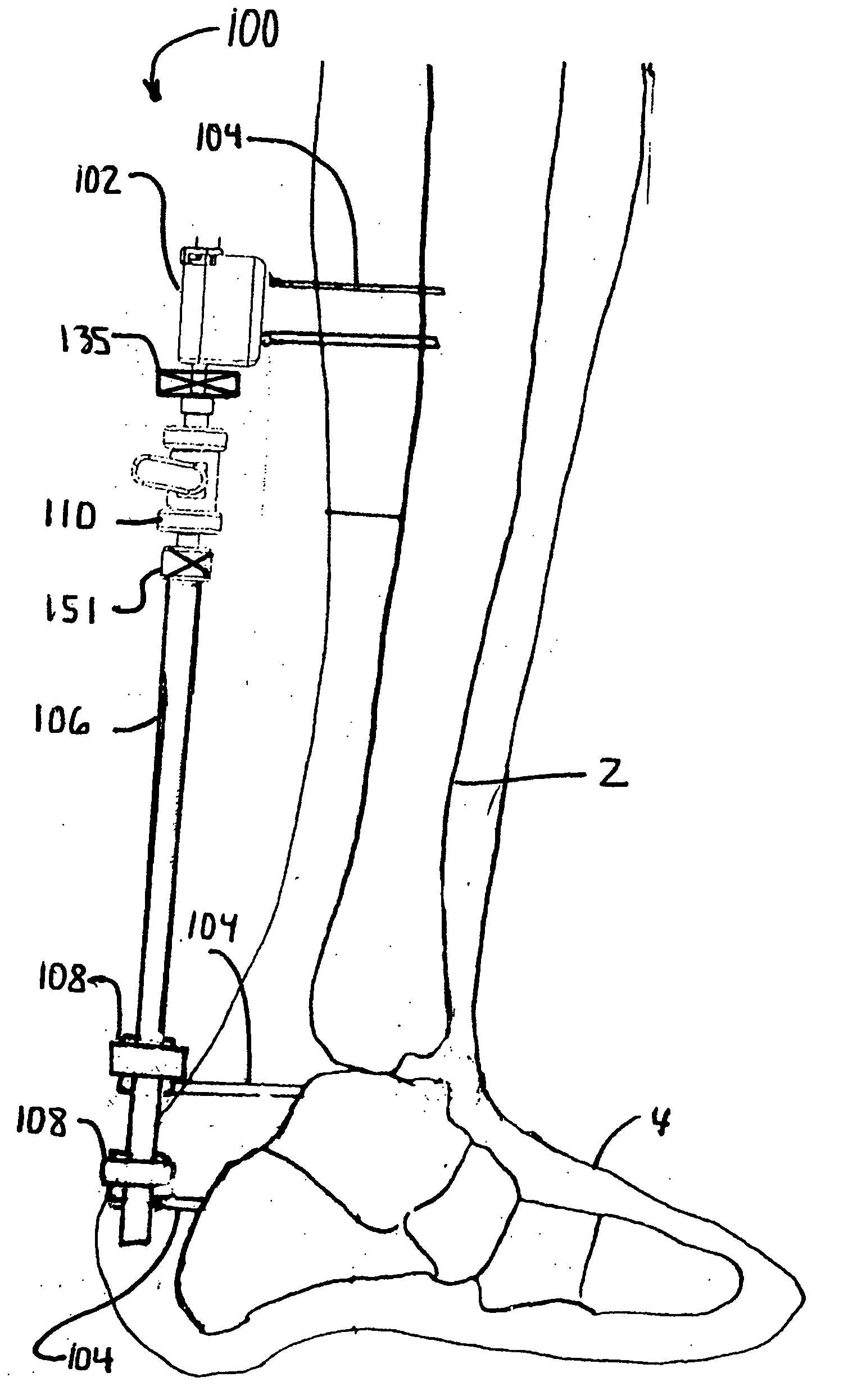
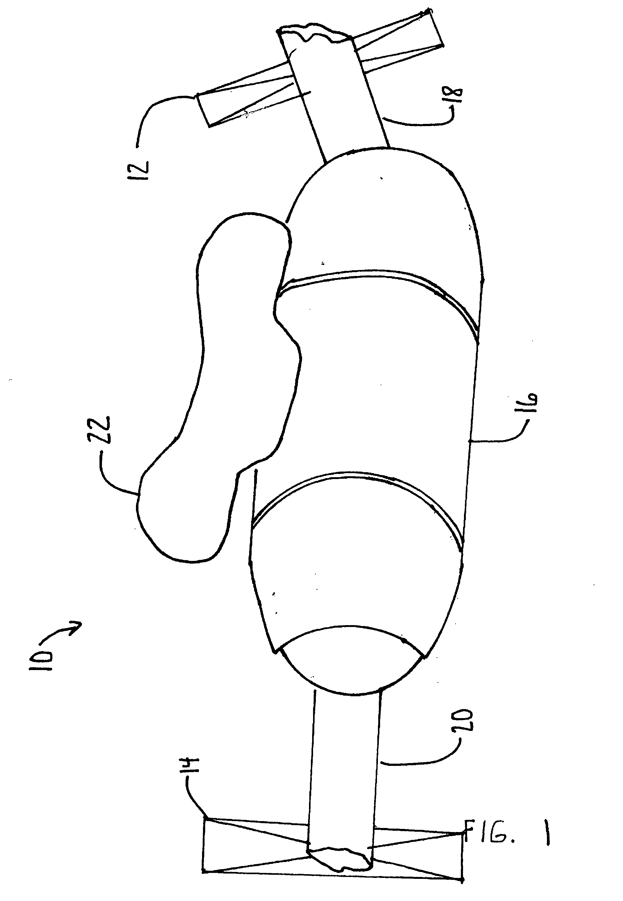
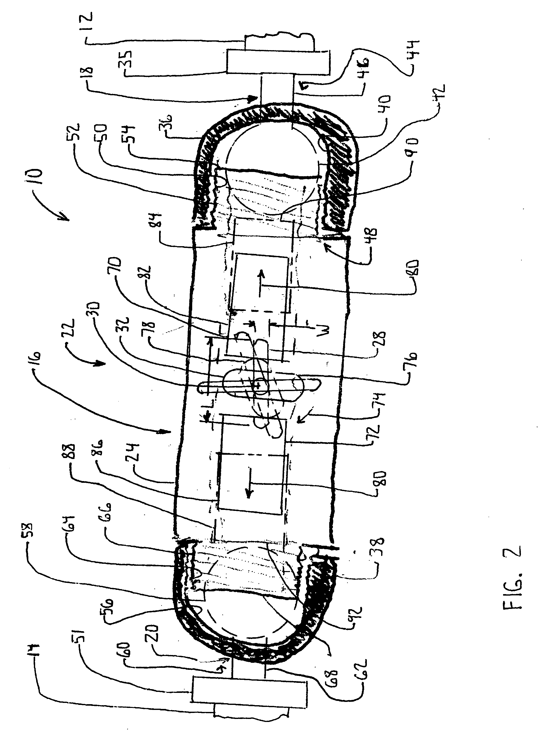
[0118] According to the present invention and referring now to FIG. 1 an articulating joint 10 is shown for rigidly connecting a first object 12 to a second object 14 for use in orthopedics. The articulating joint 10 includes a body 16 as well as a first articulating member 18. The first articulating member 18 is selectively either pivotably connected to or rigidly connected to the body 16. The first articulating member 18 is connectable to the first object 12.

[0119] The articulating joint 10 further includes a second articulating member 20. The second articulating member 20 is selectively either pivotably connected to or rigidly connected to the body 16. The second articulating member 20 is connectable to the second object 14. The first articulating member...


PUM


Abstract

An articulating joint for rigidly connecting a first object to a second object for use in orthopedics is provided. The joint includes a body and a first articulating member being selectively one of pivotably connected to and rigidly connected to the body. The first articulating member is connectable to the first object. The joint also includes a second articulating member being selectively one of pivotably connected to and rigidly connected to the body. The second articulating member is connectable to the second object. The first articulating member and second articulating member are adapted for simultaneous locking and unlocking to each other.

Description

CROSS-REFERENCE TO RELATED APPLICATIONS [0001] Cross reference is made to the following applications: DEP5427 titled, “SUPPORT FOR LOCATING INSTRUUMENT GUIDES”, DEP5597USNP titled, “METHOD OF RESECTING BONE”, DEP5368USNP titled “TRAUMA JOINT, EXTERNAL FIXATOR AND ASSOCIATED METHOD” and DEP5558USNP titled “ORTHOPAEDIC INSTRUMENT JOINT, INSTRUMENT AND ASSOCIATED METHOD” filed concurrently herewith which are incorporated herein by reference. TECHNICAL FIELD OF THE INVENTION [0002] The present invention relates generally to the field of orthopaedics, and more particularly, to a device for use in treating orthopaedic trauma. BACKGROUND OF THE INVENTION [0003] The skeletal system includes many long bones that extend from the human torso. These long bones include the femur, fibula, tibia, humerus, radius and ulna. These long bones are particularly exposed to trauma from accidents, and as such often are fractured during such trauma and may be subject to complex devastating fractures. [0004]...

Claims


Application Information

Patent Timeline
Patent Type & Authority Applications(United States)
IPC IPC(8): A61B17/00
CPCA61B17/025A61B17/15A61B17/6416A61B17/6425A61B17/6441A61B2017/0268
Inventor DEFFENBAUGH, DARENBLATT, KYLEWYSS, JOSEPHSCHNEIDER, ROBERT
Owner DEPUY PROD INC
Why Eureka
Try Eureka