Apparatus and method for spine fixation

a technology applied in the field of appendix and spine fixation, can solve the problems of adding another level of complexity to the operation, adding considerable time to the surgery, and the conduction process, so as to reduce the time and complexity of the spinal fusion operation

Inactive Publication Date: 2007-05-31
KIC VENTURES LLC
View PDF14 Cites 95 Cited by
  • Summary
  • Abstract
  • Description
  • Claims
  • Application Information

AI Technical Summary

Benefits of technology

[0013] Among the advantages of this invention may be one or more of the following. The spine fixation assembly of this invention provides a rigid and compact structure with an adjustable width. This width flexibility allows the assembly to be adapted to various size spinal anatomies without requiring contouring of the stabilizing rods. Since rod contouring is not required, the time and complexity for the spinal fusion operation are reduced.

Problems solved by technology

This contouring process may add considerable time to the surgery.
However, in most cases this adds another level of complexity to the operation and often further increases the operative time.
This increase in operative time and the complexity of the connectors put substantial stress on the surgeon and the supporting staff.
Even in the hands of the best spine surgeon, the rod is often not perfectly contoured to align with the screws.
This maneuver risks soft tissue damage and also puts the dura and the neural contents at risk for dural tears or spinal cord or nerve damage if a holding instrument slips.

Method used


Image

  • Apparatus and method for spine fixation
  • Apparatus and method for spine fixation
  • Apparatus and method for spine fixation

Examples


Embodiment Construction

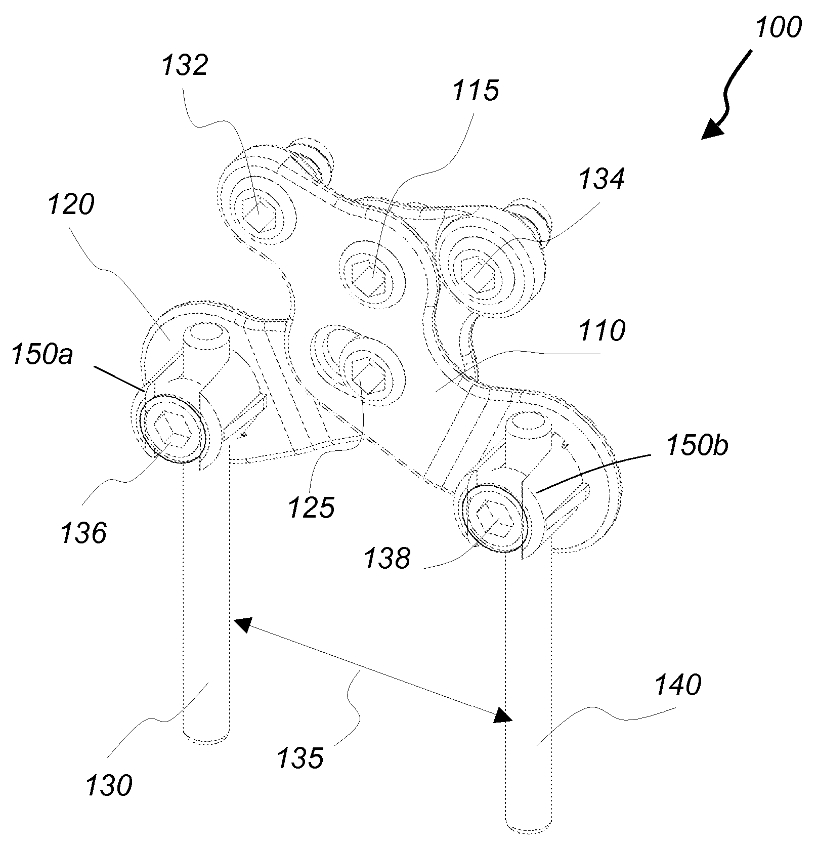
[0035] The present invention provides to a posterior cervical fixation system that utilizes a combination of rods and elongated plates arranged in an X-configuration. The spine fixation assembly includes a first s-shaped plate and a second s-shaped plate. The first and second plates are arranged in an X-configuration and are attached to each other and to the occiput via an upper central screw and a lower central screw. The upper central screw is threaded through circular shaped apertures of the first and second plates. The lower central screw is threaded through oval shaped apertures of the first and second plates. The oval shaped apertures allow the lower ends of the first and second plates to swing open or close. This action results in adjusting the distance between the lower ends of the first and second plates and thereby adjusting the width of the entire fixation assembly.

[0036] Referring to FIG. 4-FIG. 13, a posterior cervical fixation assembly 100 includes s-shaped elongated ...


PUM


Abstract

A posterior spine fixation assembly includes a first elongated plate having first and second ends and a second elongated plate having first and second ends. The first and second elongated plates are arranged in an X-shaped configuration and are attached to each other via a first screw. The assembly also includes a first elongated rod having a first end configured to be removable attached to the second end of the first elongated plate and a second elongated rod having a first end configured to be removable attached to the second end of the second elongate plate. The assembly is attached to a first spine location with the first screw. The first and second plates are configured to rotate around an axis passing through the first screw and the distance between the first elongated rod and the second elongated rod is adjusted via this rotation

Description

CROSS REFERENCE TO RELATED CO-PENDING APPLICATIONS [0001] This application is a continuation in part of U.S. application Ser. No. 10 / 669,927 filed on Sep. 24, 2003 and entitled APPARATUS AND METHOD FOR CONNECTING SPINAL VERTEBRAE the contents of which are expressly incorporated herein by reference. This application also claims the benefit of U.S. provisional application Ser. No. 60 / 759,446 filed on Jan. 17, 2006 and entitled “APPARATUS AND METHOD FOR SPINE FIXATION”, the contents of which are expressly incorporated herein by reference.FIELD OF THE INVENTION [0002] The present invention relates to an apparatus and a method for spine fixation, and more particularly to a spine fixation assembly having an adjustable width and utilizing a combination of plates and rods. BACKGROUND OF THE INVENTION [0003] The human spine comprises individual vertebras 30 (segments) that are connected to each other to form a spinal column 29, shown in FIG. 1. The vertebras 30 are separated and cushioned by...

Claims


Application Information

Patent Timeline
Patent Type & Authority Applications(United States)
IPC IPC(8): A61F2/30
CPCA61B17/7011A61B17/7044A61B17/7055A61B17/7059A61B2017/7073
Inventor CHIN, KINGSLEY R.IBARRA, MATTHEW
Owner KIC VENTURES LLC
Why Eureka
Try Eureka