
Chip card retaining mechanism

a technology of retaining mechanism and chip card, which is applied in the direction of sensing record carrier, coupling device connection, instruments, etc., can solve the problems of ineffective electrical connection between the sim card and the connector, and affect the stability of the mobile phone, and achieve the effect of stabilizing

Inactive Publication Date: 2007-06-07
SUTECH TRADING LIMITED
View PDF6 Cites 17 Cited by
  • Summary
  • Abstract
  • Description
  • Claims
  • Application Information

AI Technical Summary

Benefits of technology

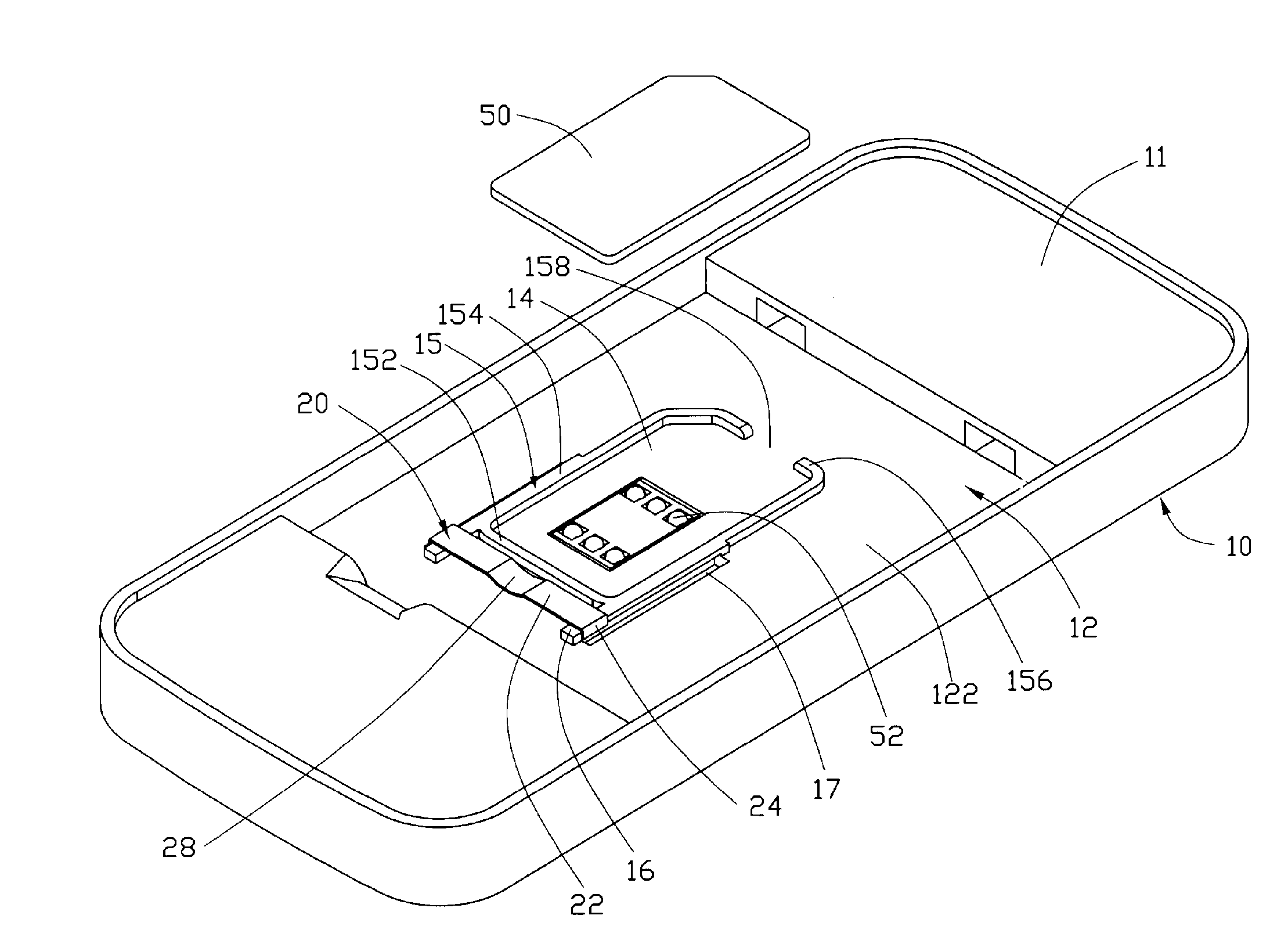
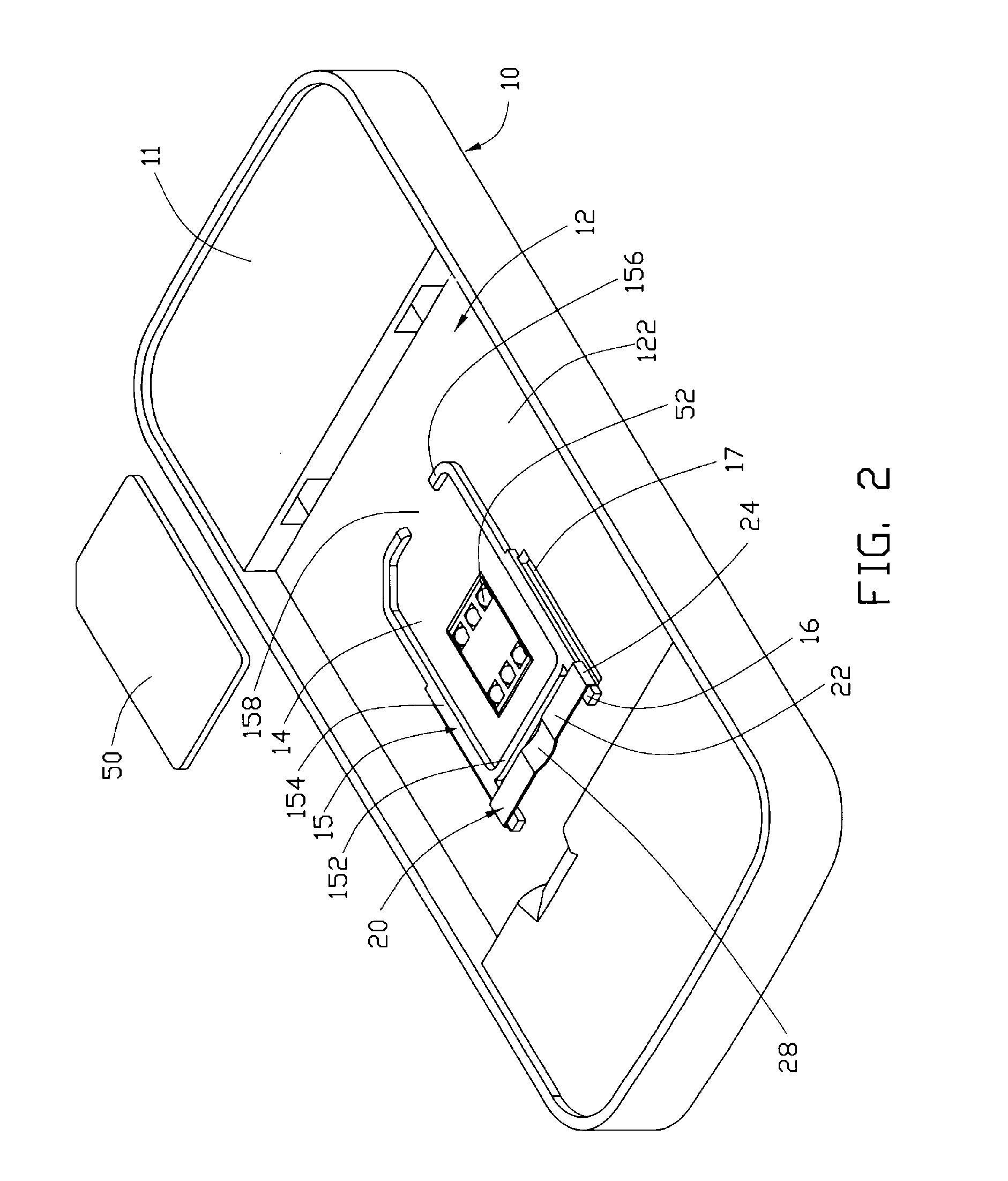
[0006] In a first preferred embodiment, a chip card retaining mechanism for retaining a chip card mounted in an electronic device, the electronic device including a housing. The chip card retaining mechanism comprises a receiving portion, and a locking member. The receiving portion is formed on the housing for fittingly receiving the chip card therein. The locking member is slidably mounted on the housing and positioned over the receiving portion such that if the chip card is received in the receiving portion, the locking member can stably lock the chip card in the receiving portion.

Problems solved by technology

Although the locking element 54 can be easily moved to assembly the SIM card, when a mobile phone inadvertently undergoes impact, this impact may result in an outer force which removes the locking element 54 remove from the receiving groove 520, which can result in an ineffective electrical connection between the SIM card and the connector 50.
At worst, the SIM card may become completely separated from the receiving groove 520, which badly affects stability of the mobile phone.

Method used


Image

  • Chip card retaining mechanism
  • Chip card retaining mechanism
  • Chip card retaining mechanism

Examples


Embodiment Construction

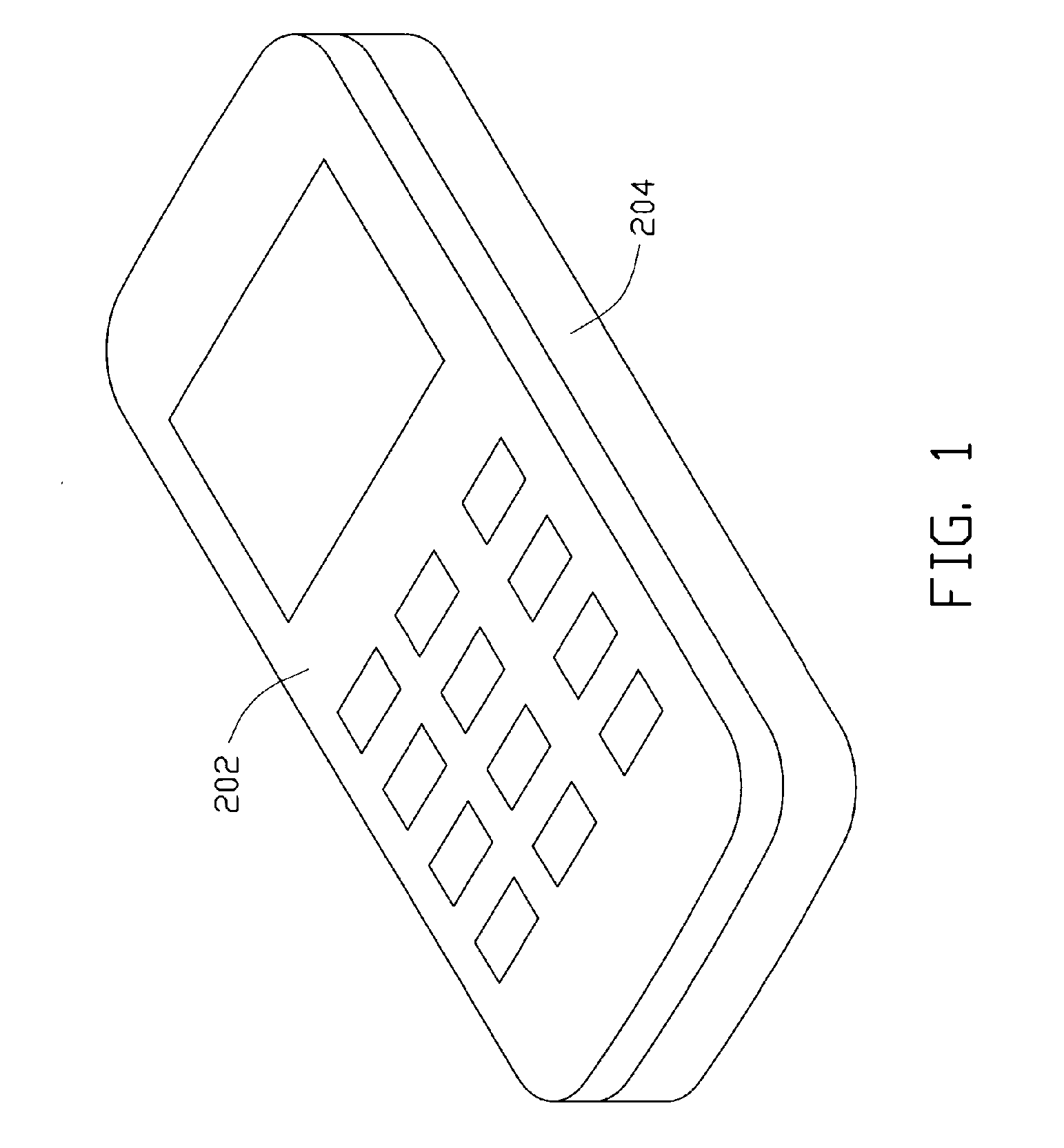
[0014] A chip card retaining mechanism is adapted for retaining a chip card in an electronic device such that the chip card is electrically connected with a connector in the electronic device. Referring to FIG. 1, the chip card retaining mechanism is applied to an exemplary mobile phone 200, which includes a front cover 202, a housing 10, and a rear cover 204. The front cover 202 and the rear cover 204 cooperatively define an enclosed space. The housing 10 is mounted in the enclosed space. Referring to FIG. 2, in order to identify the used mobile phone, when communicating, a chip card 50, such as a subscriber identification module, also called SIM card, is provided. The housing 10 has a battery compartment 12 (partly shown) defined in an upper surface portion 11 thereof and defined by a bottom surface 122. The chip card 50 is electrically connected to a printed circuit board (PCB, not shown) by a connector 52. The battery compartment 12 is for receiving a battery (not shown).

[0015]...


PUM


Abstract

A chip card retaining mechanism for retaining a chip card (50) mounted in an electronic device, the electronic device including a housing (10). The chip card retaining mechanism includes a receiving portion, and a locking member (20). The receiving is formed on the housing for fittingly receiving the chip card therein. The locking member is slidably mounted on the housing and positioned over the receiving portion such that if the chip card is received in the receiving portion, the locking member stably locks the chip card in the receiving portion.

Description

FIELD OF THE INVENTION [0001] The present invention generally relates to chip card retaining mechanisms and, more particularly, to a chip card retaining mechanism for seating a chip card in an electronic device such as a mobile phone. DESCRIPTION OF RELATED ART [0002] Nowadays, electronic devices such as mobile phones are widely used and bring convenience to our lives, as such, electronic devices have become a part of modern life. Every electronic device has a chip card such as a SIM (subscriber identification module) card for carrying information necessary for operating the mobile phone. The chip card may also contain personal information for the subscriber, for example, a listing of frequently used telephone numbers. However, it is necessary to provide a chip card retaining mechanism to hold the chip card in the electronic device. [0003] Referring to FIG. 5, a typical chip card retaining mechanism used in a mobile phone is as follows. The chip card retaining mechanism includes a m...

Claims


Application Information

Patent Timeline
Patent Type & Authority Applications(United States)
IPC IPC(8): G06K7/06G06K7/00
CPCG06K7/0021G06K13/085H01R13/2442H01R2201/16
Inventor JIANG, MAO-FACHEN, CHIA-HUA
Owner SUTECH TRADING LIMITED
Learn More