Apparatus and method for restraining and deploying an airfoil

a technology of airfoils and apparatuses, applied in the field of airfoils, can solve the problems of airfoils presenting significant aerodynamic drag, vehicle difficulties in attaining aerodynamic stability, and their positions may oscillate, and achieve the effect of causing rotational oscillation

Inactive Publication Date: 2007-06-07
LOCKHEED MARTIN CORP
View PDF37 Cites 33 Cited by
  • Summary
  • Abstract
  • Description
  • Claims
  • Application Information

AI Technical Summary

Benefits of technology

[0013] Therefore, it is an object of the present invention to provide an improved apparatus and method for restraining and deploying an airfoil.
[0018] The present invention provides significant advantages, including: (1) providing a means to stow airfoils of a vehicle without the use of clips or the like; (2) allowing a vehicle to become aerodynamically stable with airfoils of the vehicle only partially deployed; and (3) damping rotational oscillations in the airfoils of a vehicle.

Problems solved by technology

Because the vehicle's deployment velocity is often slow relative to the operational velocity of the vehicle, the airfoils present significant aerodynamic drag.
Accordingly, the vehicle may have difficulties in attaining aerodynamic stability.
Moreover, when conventional, stowable airfoils are deployed, their positions may oscillate between the fully deployed positions and positions just short of the fully deployed positions.
Such oscillations result in changes to the aerodynamic characteristics of the airfoils and inefficient airfoil aerodynamic operation.
Problems may arise, however, if one or more of the clips are not removed from the vehicle.
In such a situation, the restrained control surface may inhibit the launched vehicle's ability to properly maneuver, causing the vehicle to become aerodynamically or hydrodynamically unstable.
The removed clips may also cause damage if they impact other equipment near the launch site.
Such restraining systems are often bulky and heavy, which may impact the performance of the vehicle.

Method used


Image

  • Apparatus and method for restraining and deploying an airfoil
  • Apparatus and method for restraining and deploying an airfoil
  • Apparatus and method for restraining and deploying an airfoil

Examples


Embodiment Construction

[0037] Illustrative embodiments of the invention are described below. In the interest of clarity, not all features of an actual implementation are described in this specification. It will of course be appreciated that in the development of any such actual embodiment, numerous implementation-specific decisions must be made to achieve the developer's specific goals, such as compliance with system-related and business-related constraints, which will vary from one implementation to another. Moreover, it will be appreciated that such a development effort might be complex and time-consuming but would nevertheless be a routine undertaking for those of ordinary skill in the art having the benefit of this disclosure.

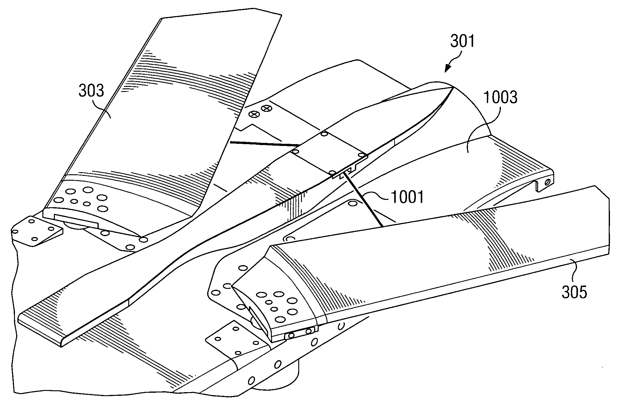
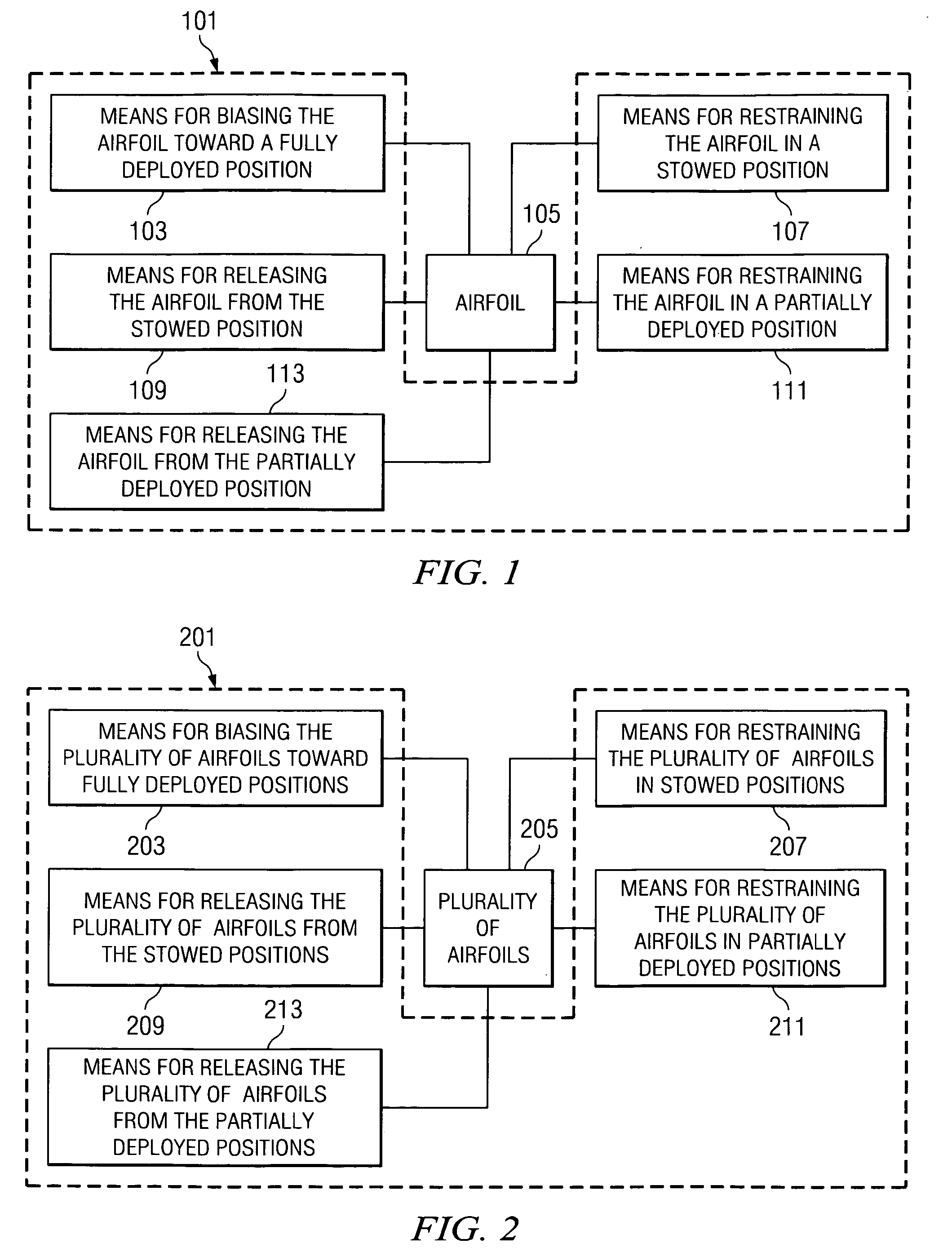
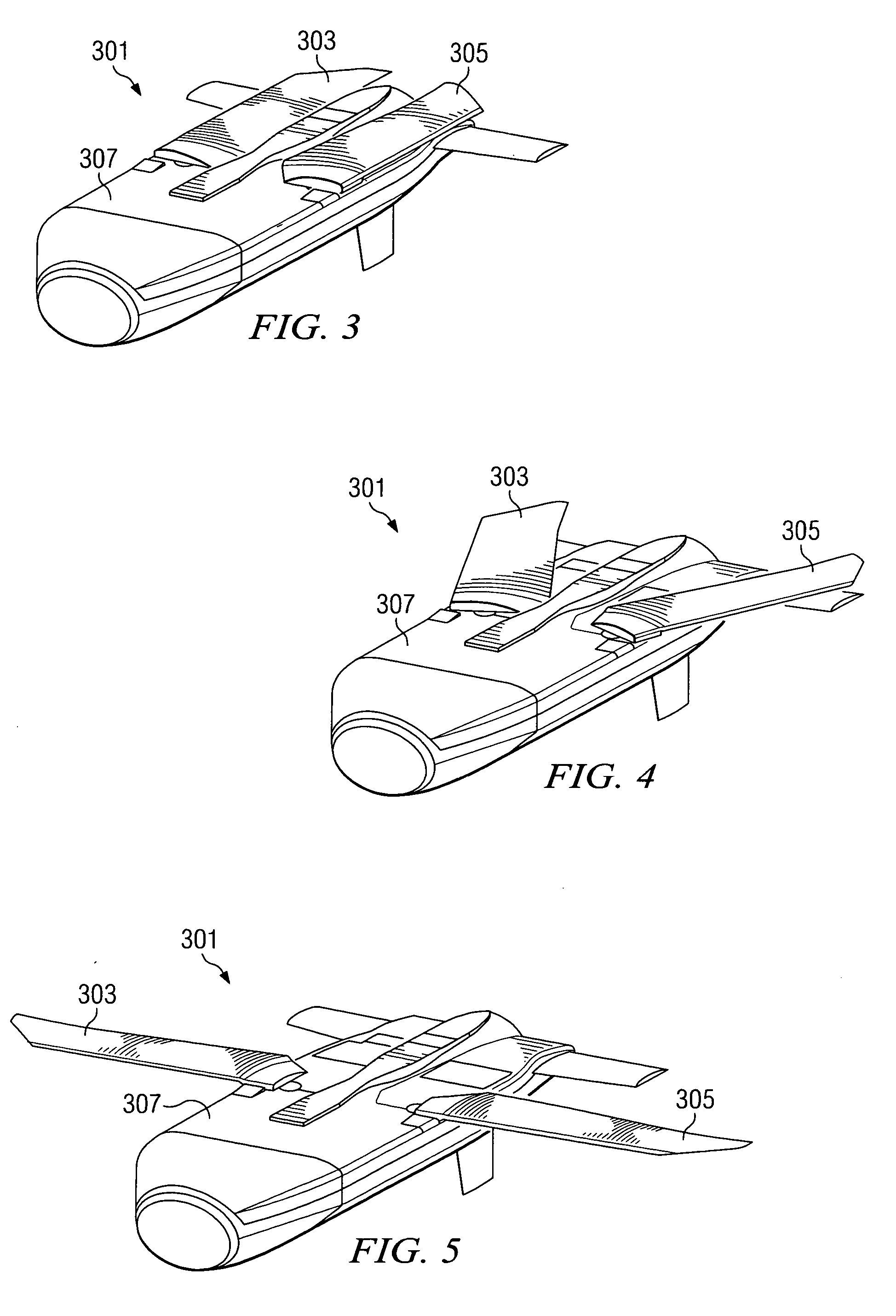
[0038] The present invention represents an apparatus for restraining and deploying one or more airfoils of a vehicle and a method of using the apparatus. Generally, the apparatus restrains one or more airfoils in fully stowed positions until such time that the airfoils are to be...


PUM


Abstract

An apparatus includes means for biasing a first airfoil of a vehicle toward a fully deployed position, means for restraining the first airfoil in a stowed position, means for releasing the first airfoil from the stowed position, means for restraining the first airfoil in a partially deployed position, and means for releasing the first airfoil from the partially deployed position. A method includes restraining an airfoil in a stowed position, releasing the airfoil from the stowed position, and biasing the airfoil from the stowed position toward a fully deployed position. The method further includes restraining the airfoil in a partially deployed position, releasing the airfoil from the partially deployed position, and biasing the airfoil from the partially deployed position toward the fully deployed position.

Description

STATEMENT REGARDING FEDERALLY SPONSORED RESEARCH OR DEVELOPMENT [0001] The U.S. Government has a paid-up license in this invention and the right in limited circumstances to require the patent owner to license others on reasonable terms as provided for by the terms of contract number F08630-03-D-0103 0001 awarded by the United States Air Force.BACKGROUND [0002] 1. Field of the Invention [0003] The present invention relates to airfoils. In particular, the present invention relates to an apparatus for restraining and deploying an airfoil and a method of using the apparatus. [0004] 2. Description of Related Art [0005] Vehicles that traverse a fluid medium, such as rockets, missiles, projectiles, torpedoes, pods, drones, and the like generally have one or more airfoils, such as wings, fins, or other such control surfaces, which are used to stabilize and / or steer the vehicle as it moves through the fluid medium. It is often desirable to fold, rotate, or pivot such control surfaces so that...

Claims


Application Information

Patent Timeline
Patent Type & Authority Applications(United States)
IPC IPC(8): F42B10/14
CPCF42B10/14
Inventor JANKA, RONALD E.
Owner LOCKHEED MARTIN CORP
Why Eureka
Try Eureka