Resonant power converter for radio frequency transmission and method

a technology of radio frequency transmission and power converter, which is applied in the field of radio frequency signals, can solve the problems of not providing any means for converting power to an rf carrier frequency, no means taught in the aforesaid disclosure, and the obvious less than optimal use of battery power, so as to improve the charging switch apparatus and reduce power consumption

Active Publication Date: 2011-04-12
STMICROELECTRONICS SRL
View PDF37 Cites 12 Cited by
  • Summary
  • Abstract
  • Description
  • Claims
  • Application Information

AI Technical Summary

Benefits of technology

[0025]In a sixth aspect of the invention, an improved charging switch apparatus is disclosed. In one exemplary embodiment, charging switches a

Problems solved by technology

This is obviously less than optimal usage of battery power.
There are no means taught in the aforesaid disclosure, however, for generating enough power to drive the line directly without the need for an active power amplifier.
Also, the aforesaid disclosure does not provide any means for converting power to an RF carrier frequency, as the described system is a low frequency baseband transmission system rather than an RF passband transmission system.
When the transmitter is on, it typically generates noise or distortion that can fall into the receive band.
A particularly difficult problem in using noise-shaping encoders in full-duplex transceivers is that high levels of quantization noise are generated out of band, and this may even further corrupt the receive band.
If an analog RF filter with 80 dB of suppression over this whole frequency range existed in the current state-of-the-art, it would necessarily have a high insertion loss, and would also be comparatively expensive.
Therefore,

Method used


Image

  • Resonant power converter for radio frequency transmission and method
  • Resonant power converter for radio frequency transmission and method
  • Resonant power converter for radio frequency transmission and method

Examples


example 1

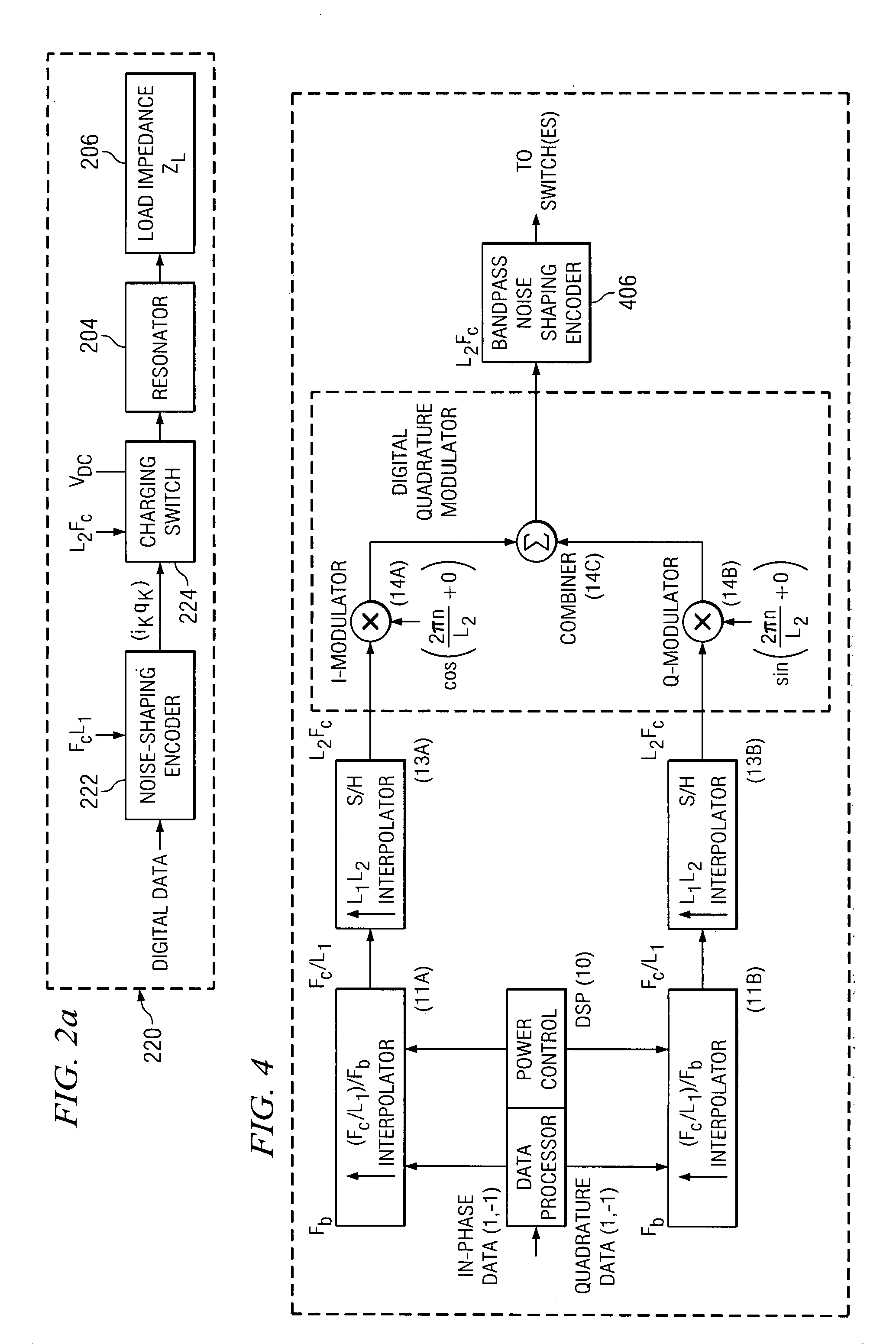
[0074]Referring back to the embodiment of FIG. 3, we choose L1=1 and L2=4. We also set the phase offset, θ=0, inside the cos( ) and sin( ) arguments driving the I- and Q-modulators. Data sample {ik} is the kth sample coming from the in-phase encoder 302a, and similarly, data sample {qk} is the kth sample coming from the quadrature encoder 302b. Using a clock at a rate 4Fc, which is four times higher than the carrier frequency Fc, samples from the encoders are effectively sampled and held by interpolators 318 four successive times before the next kth sample arrives. I- and Q-modulators 320 are effectively arithmetic multipliers. The multipliers each have two inputs and one output. I-modulator 320a receives the in-phase samples from interpolator 318a, and also receives a periodic sequence {1, 0, −1, 0}, which is the result of the trigonometric operation cos(2πn / 4), the in-phase version of the carrier frequency Fc having four samples per carrier cycle. Similarly, Q-modulator 320b recei...

example 2

[0075]As in the previous EXAMPLE 1, L1=1 and L2=4. This time, however, the phase offset, θ=π / 4, is set inside the cos( ) and sin( ) arguments driving the I- and Q-modulators. Note that setting the phase offset to π / 4 is important in some instances. In particular, the CDMA standards of IS-95, IS-95a, IS-98, and IS-2000 call for a π / 4 offset QPSK as a mode of modulation. It is well known to one of ordinary skill in the art of data modulation, that using π / 4 offset QPSK, as opposed to zero offset, has the benefit of reducing the peak-to-average, otherwise known as the crest factor. Going back to the prior description of operation, data sample {ik} is the kth sample coming from the in-phase encoder 302a, and similarly, data sample {qk} is the kth sample coming from the quadrature encoder 302b. Using a clock at a rate 4Fc, which is four times higher than the carrier frequency Fc, samples from the encoders are effectively sampled and held by interpolators 318 four successive times before ...

example 3

[0078]As in the previous EXAMPLE 2, L1=1, L2=4, and θ=π / 4. However, ternary quantization is used within the noise-shaping encoders 302. Therefore, there are nine possible data sequences every carrier cycle, and the constellation map would consist of a rectangular arrangement of nine symbol points at the following I-Q coordinates: (1,0), (1,1), (0,1), (−1,1), (−1,0), (−1, −1), (0,−1), (1,−1), and (0,0). The nine possible data sequences corresponding to these nine symbol points on the constellation map would therefore be: {1,−1,−1,1}, {2,0,−2,0}, {1,1,−1,−1}, {0,2,0,−2}, {−1,1,1,−1}, {−2,0,2,0 }, {−1,−1,1,1}, {0,−2,0,2}, {0,0,0,0}.


PUM


Abstract

A resonant power converter for ultra-efficient radio frequency transmission and associated methods. In one exemplary embodiment, the invention is digitally actuated and uses a combination of a noise-shaped encoder, a charging switch, and a high-Q resonator coupled to an output load, typically an antenna or transmission line. Energy is built up in the electric and magnetic fields of the resonator, which, in turn, delivers power to the load with very little wasted energy in the process. No active power amplifier is required. The apparatus can be used in literally any RF signal application (wireless or otherwise), including for example cellular handsets, local- or wide-area network transmitters, or even radio base-stations.

Description

PRIORITY[0001]This application claims priority benefit of U.S. provisional patent application Ser. No. 60 / 361,812 entitled “RESONANT POWER CONVERTER FOR RADIO FREQUENCY TRANSMISSION AND METHOD” filed Mar. 4, 2002, which is incorporated by reference herein in its entirety.RELATED APPLICATIONS[0002]This application is related to co-owned and U.S. patent application Ser. No. 10 / 382,326 entitled “CODER APPARATUS FOR RESONANT POWER CONVERSION AND METHOD” filed contemporaneously herewith, which claims priority benefit of U.S. provisional patent application Ser. No. 60 / 361,813 of the same title filed Mar. 4, 2002, both of which are incorporated by reference herein in their entirety.1. FIELD OF THE INVENTION[0003]The present invention relates generally to radio frequency signals, and specifically to apparatus and methods for radio frequency (RF) signal transmission, reception, and / or modulation.2. DESCRIPTION OF RELATED TECHNOLOGY[0004]As is well understood, the so-called “PAE” (Power Added...

Claims


Application Information

Patent Timeline
IPC IPC(8): H04L27/00H03C3/40H04B1/04
CPCH03C3/40H04B1/04Y02B60/50
Inventor NORSWORTHY, STEVEN R.NORSWORTHY, ROSS W.
Owner STMICROELECTRONICS SRL
Why Eureka
Try Eureka