Multiple telescoping tube comprising a load-controlled locking device

Inactive Publication Date: 2007-06-07
CAMERA DYNAMICS
View PDF10 Cites 1 Cited by
  • Summary
  • Abstract
  • Description
  • Claims
  • Application Information

AI Technical Summary

Benefits of technology

[0017] As mentioned above, at least one of the inner tubes may be arranged in one of the outer tubes. This enables a particularly space-saving design of the multiple telescopic tube.

Problems solved by technology

This is laborious, particularly in the case of rapid and frequent changes of camera set-up.

Method used


Image

  • Multiple telescoping tube comprising a load-controlled locking device
  • Multiple telescoping tube comprising a load-controlled locking device
  • Multiple telescoping tube comprising a load-controlled locking device

Examples


Embodiment Construction

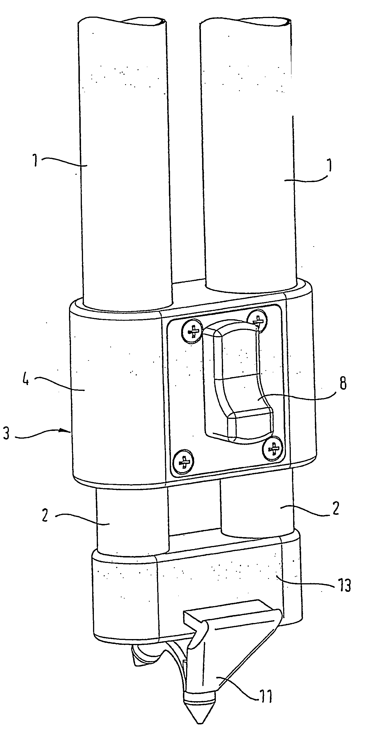
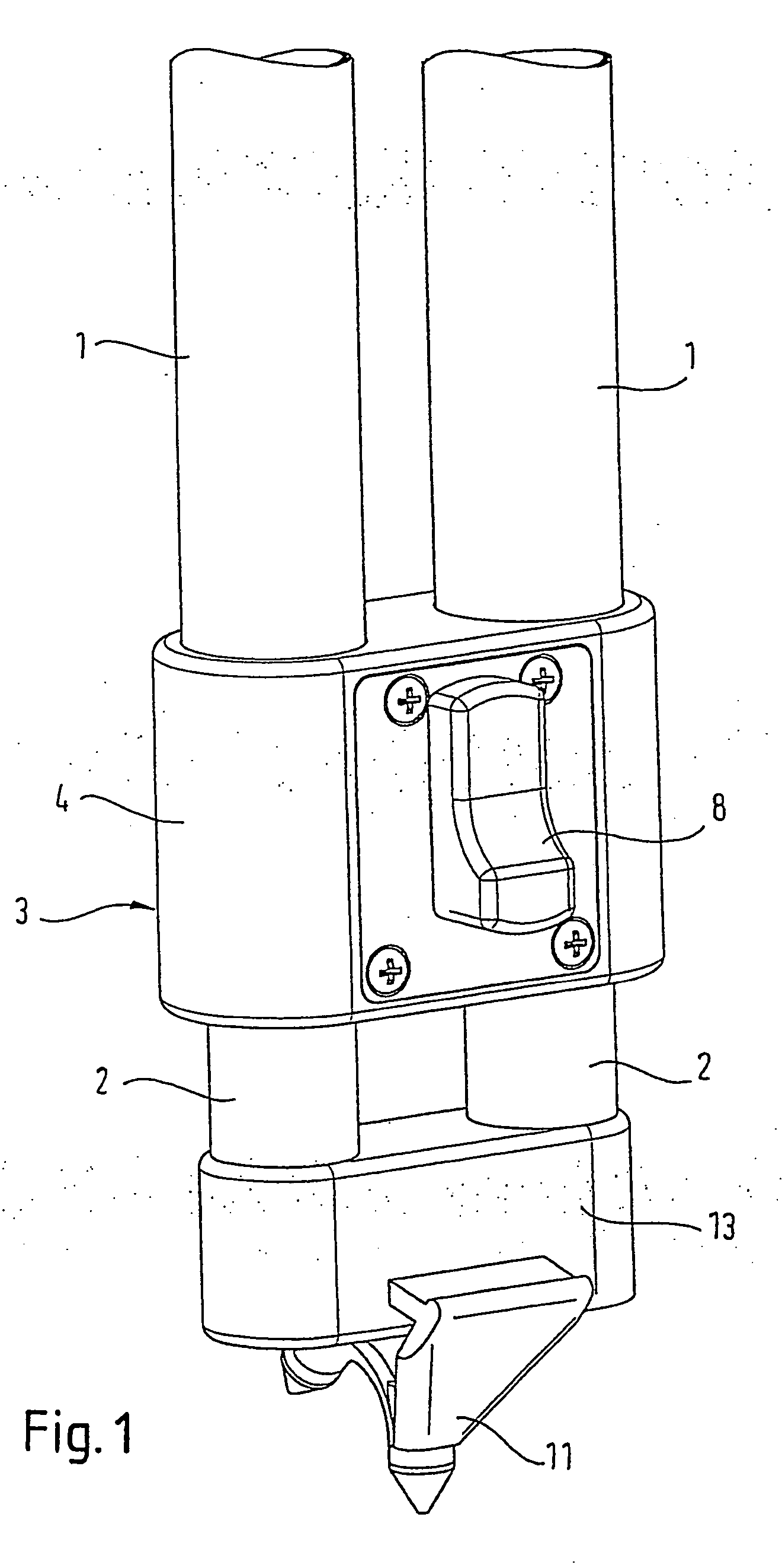
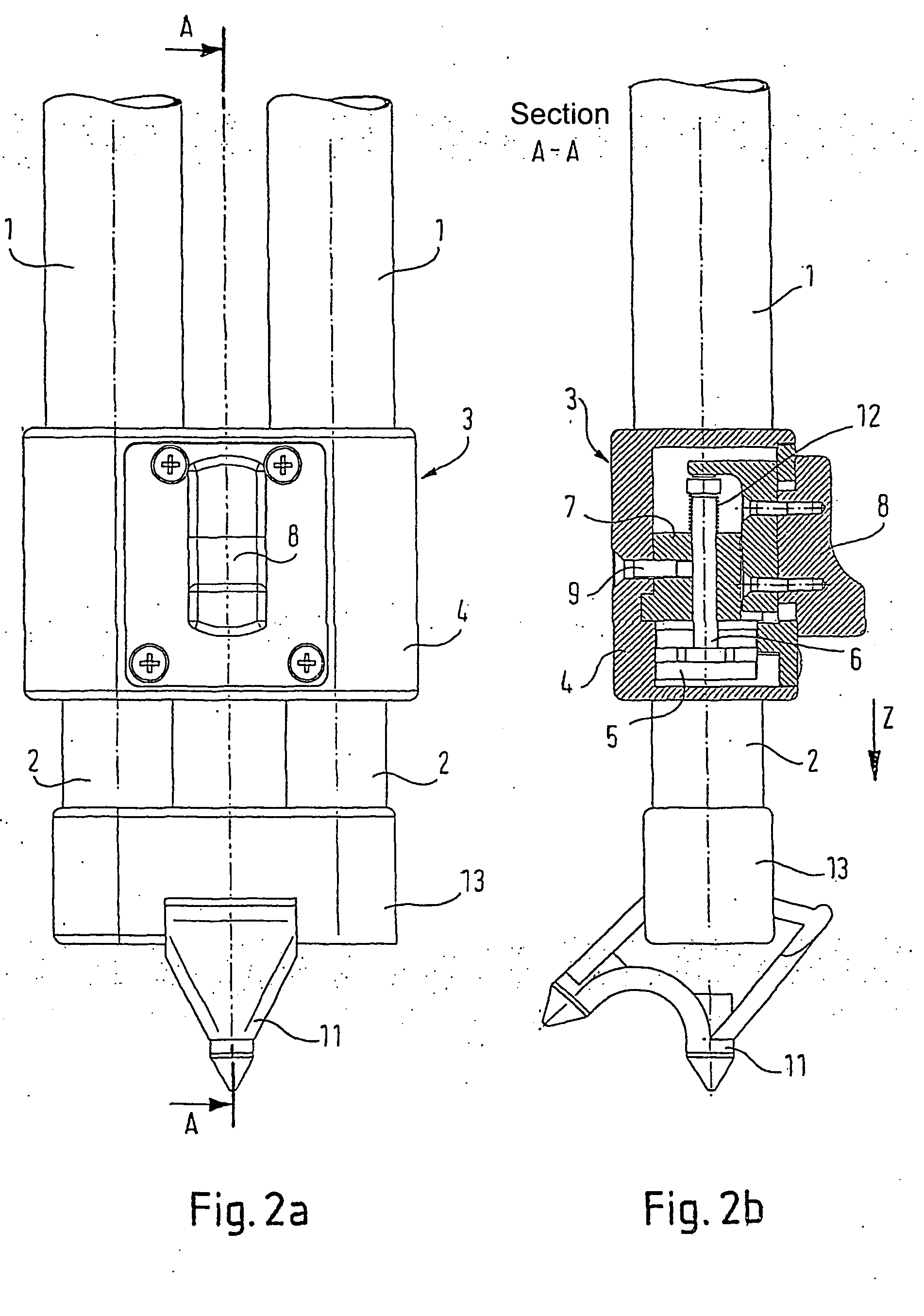
[0032] An advantageous embodiment of a multiple telescopic tube according to the invention is illustrated in FIGS. 1 to 4.

[0033] The double telescopic tube according to the embodiment illustrated here is particularly suitable for use as a stand leg of a camera stand, for instance a monopod stand or a tripod stand. It has two outer tubes 1 and two inner tubes 2. The inner tubes 2 are arranged slideably displaceable in the outer tubes 1, such that the length of the stand leg is steplessly adjustable.

[0034] The material used for the inner tubes 2 and the outer tubes 1 is preferably a light material such as carbon fibre or aluminium.

[0035] In order to fix the inner tubes 2 in relation to the outer tubes 1 and thus to adjust the stand leg at a desired length, a clamping device 3 is provided. The housing 4 of this clamping device 3 is firmly linked to the two outer tubes 1.

[0036] The two inner tubes 2 are rigidly coupled together at their lower ends via a cross-bar 13, on which is pro...


PUM


Abstract

Disclosed is a multiple telescopic tube comprising at least two parallel outer tubes (1), at least two inner tubes (2) which are disposed parallel to the outer tubes (1) and are movable relative to said outer tubes (1) in a longitudinal direction (Z), and a clamping device (3) which is provided with a clamping engagement element (5) that can be made to engage with the exterior surfaces of the inner tubes (2). The clamping device (3) prevents displacement of the inner tubes (2) relative to the outer tubes (1) in a longitudinal clamping direction while the inner tubes (2) remain movable in the opposite longitudinal direction when the multiple telescopic tube is subjected to a load in said longitudinal clamping direction. The inventive multiple telescopic tube can be used as a leg of a camera stand, for example.

Description

TECHNICAL FIELD [0001] The present invention relates to a multiple telescopic tube. The term “multiple” implies that at least two outer tubes arranged parallel to each other and at least two inner tubes arranged parallel to the outer tubes are provided, the inner tubes being displaceable relative to the outer tubes in the longitudinal direction, and specifically steplessly displaceable. The term also implies, however, that at least two tubes are provided and are displaceable into each other, in the telescoping direction. A clamping device serves to lock the inner tubes relative to the outer tubes in any desired relative position. [0002] Multiple telescopic tubes of this type are usable particularly as legs for camera stands. For instance, in the case of a tripod camera stand, three such multiple telescopic tubes are provided, each forming a stand leg. [0003] The term “telescopic tube” implies in the following that the inner tubes are displaceable parallel to the outer tubes in order...

Claims


Application Information

Patent Timeline
Patent Type & Authority Applications(United States)
IPC IPC(8): F16M11/00F16B7/14F16M11/26F16M11/32
CPCF16B7/1418F16M11/26F16M11/32F16M11/28F16M2200/027
Inventor HEIN, DIETER
Owner CAMERA DYNAMICS
Why Eureka
Try Eureka