Shield device with receiving cages

a shield device and receiving cage technology, applied in shielding, nuclear engineering, nuclear elements, etc., can solve the problems of failure of testing and unaddressed need in the industry

Active Publication Date: 2007-06-07
HON HAI PRECISION IND CO LTD
View PDF15 Cites 5 Cited by
  • Summary
  • Abstract
  • Description
  • Claims
  • Application Information

AI Technical Summary

Problems solved by technology

However, in the testing process, ambient electromagnetic waves may enter the shield cage via the through hole 86, and interfere with testing of the circuit boar...

Method used


Image

  • Shield device with receiving cages
  • Shield device with receiving cages
  • Shield device with receiving cages

Examples


Embodiment Construction

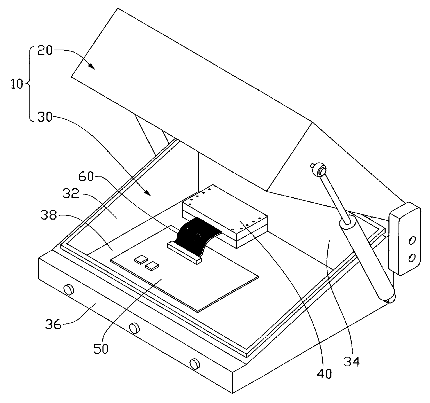
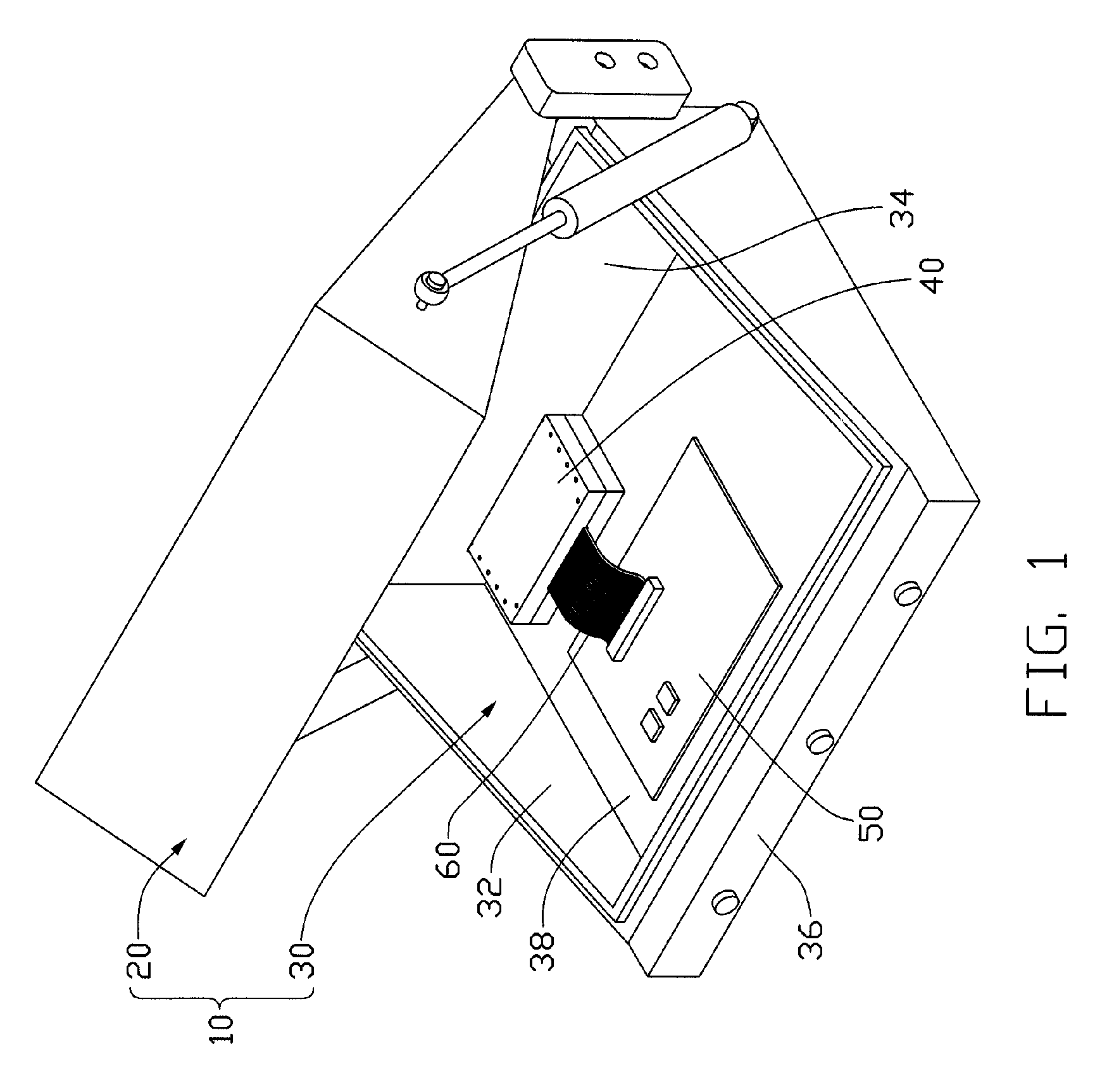
[0013] Referring to FIG. 1, an assembled view of a shield device in accordance with an exemplary embodiment of the present invention is used for blocking ambient electromagnetic waves from interfering with testing of an electronic product 50, such as, a circuit board, a mobile phone, and so on, connected with a connective means like a flexible cable 60. The shield device comprises a shield cage 10 for accommodating the electronic product 50, and a receiving cage for receiving the flexible cable 60.

[0014] The shield cage 10 comprises a lid 20 and a base 30. The lid 20 and the base 30 contain electromagnetic wave absorbing materials (not shown) to minimize internal electromagnetic wave reflections in the shield cage 10 during a test.

[0015] The lid 20 is generally rectangular in shape, and is movable between a sealed position and an open position relative to the base 30.

[0016] The base 30 is generally rectangular in shape, and comprises a pair of opposite sidewalls 32, a back wall 3...


PUM


Abstract

A shield device for blocking ambient electromagnetic waves from interfering with testing of an electronic product (50) connected with a cable (60), includes a shield cage (10) and a receiving cage (40) for receiving the cable. The shield cage includes a base (30) defining a receiving space (38) for receiving the electronic product, and an opening in communication with the receiving space. The receiving cage received in the opening, includes an upper cover (42) and a lower cover (44). The upper cover defines a recessed portion (422), and the lower cover includes a protrusion (442) received in the recessed portion. When the upper cover is mounted on the lower cover, at least one transition portion (46) is formed in the receiving cage.

Description

FIELD OF THE INVENTION [0001] The present invention relates to shield devices, and particularly to a shield device with a receiving cage for receiving cables. DESCRIPTION OF RELATED ART [0002] With the rapid development of electronic technology, electronic products, such as, mobile phones, wireless access points, circuit boards, and so on, include more and more functions. During a production process, the electronic products are generally undergone different tests in order to ensure quality of the electronic products. Often, the electronic product is mounted in a shield cage to test whether various functions of the electronic product meet standard requirements. [0003] Referring to FIG. 6, a conventional shield cage is shown. The shield cage includes a cover 70 and a base 80. The base 80 includes four sidewalls 82 and a receiving space 84 bounded by the sidewalls 82. A through hole 86 is defined in one of the sidewalls 82. During a testing process, an electronic product, such as, a ci...

Claims


Application Information

Patent Timeline
IPC IPC(8): G21F3/00
CPCH05K9/0069
Inventor CHANG, PING-CHUNLEE, CHAO-CHIEN
Owner HON HAI PRECISION IND CO LTD
Why Eureka
Try Eureka