System and method for a pump with reduced form factor

a technology of form factor and pump, which is applied in the direction of pump parameter, piston pump, positive displacement liquid engine, etc., can solve the problems of sharp pressure spikes in liquid, high cost of photochemicals used in the semiconductor industry, and high cost of up to $1000 a liter, so as to reduce fluid usage, reduce the form factor, and improve the effect of fluid handling ability

Active Publication Date: 2007-06-07
ENTEGRIS INC
View PDF99 Cites 63 Cited by
  • Summary
  • Abstract
  • Description
  • Claims
  • Application Information

AI Technical Summary

Benefits of technology

[0006] Embodiments of the present invention provide a multi-stage pump with a reduced form factor, gentler fluid handling capabilities and various features to reduce fluid usage and increase reliability. One embodiment of the present invention includes a multi-stage pump comprising an pump inlet flow path, a pump outlet flow path, a feed pump in fluid communication with the pump inlet flow path, a dispense pump in fluid communication with the feed pump and the pump outlet flow path, and a set of valves to selectively allow fluid flow through the multi-stage pump. The feed pump can comprise a feed stage diaphragm movable in a feed chamber, a feed piston to move the feed stage diaphragm and a feed motor coupled to the feed piston to reciprocate the feed piston. The dispense pump can comprise a dispense rolling diaphragm movable in a dispense chamber, a dispense piston to move the dispense diaphragm and a dispense motor coupled to the dispense piston to reciprocate the dispense piston. According to various embodiments of the present invention the feed stage diaphragm can also be a rolling diaphragm. Additionally, the feed motor and dispense motor can each be stepper motors or brushless DC motors or, for example, the feed motor can be a stepper motor and the dispense motor a brushless DC motor. The multi-stage pump, according to one embodiment can include a single piece dispense block that at least partially defines the dispense chamber, the feed chamber and various flow paths in the multi-stage pump.
[0011] Various embodiments of the present invention can include features to make the pump drip proof, such as offsets at intersections between PTFE and metal parts, features to guide drips away from electronics and various seals. Additionally, embodiments of the present invention can include features to reduce the affects of heat on the fluid in the pump. For example, electronic components that generate heat, such as solenoids or microchips, can be positioned away from the dispense block to the extent allowed by space constraints.
[0012] Embodiments of the present invention provide a multi-stage pump that has a small-form factor (e.g., approximately ½ the size of previous multi-stage pumps) with gentler fluid handling properties and a wider range of operation. Multi-stage pumps according to embodiments of the present invention have 35% fewer parts than previous multi-stage pumps, leading to a reduction in cost and complication, and do not require significant if any hydraulics. Multi-stage pumps, according to embodiments of the present invention, are easily maintained in the field, use less process chemical for dispense operations, reduce outgassing for sensitive chemistries and provide for more precise control. Other advantages include increased resist savings, increased uptime, higher yield and lower maintenance costs. Additionally, multi-stage pumps according to embodiments of the present invention provide significant space savings, allowing more pumps to be fit in the same amount of space as previous pumps.

Problems solved by technology

Many photochemicals used in the semiconductor industry today are very expensive, frequently costing as much as $1000 a liter.
Current multiple stage pumps can cause sharp pressure spikes in the liquid.
Such pressure spikes and subsequent drops in pressure may be damaging to the fluid (i.e., may change the physical characteristics of the fluid unfavorably).
Additionally, pressure spikes can lead to built up fluid pressure that may cause a dispense pump to dispense more fluid than intended or dispense the fluid in a manner that has unfavorable dynamics.
The spaces between the various plates increased the likelihood of fluid leakage.
Additionally, valves were distributed throughout the pump, making replacement and repair more difficult.

Method used


Image

  • System and method for a pump with reduced form factor
  • System and method for a pump with reduced form factor
  • System and method for a pump with reduced form factor

Examples


Embodiment Construction

[0042] Preferred embodiments of the present invention are illustrated in the FIGUREs, like numerals being used to refer to like and corresponding parts of the various drawings. To the extent dimensions are provided, they are provided by way of example for particular implementations and are not provided by way of limitation. Embodiments can be implemented in a variety of configurations.

[0043] Embodiments of the present invention are related to a pumping system that accurately dispenses fluid using a multiple stage (“multi-stage”) pump with reduced form factor. Embodiments of the present invention can be utilized for the dispense of photo-resist and other photosensitive chemicals in semiconductor manufacturing.

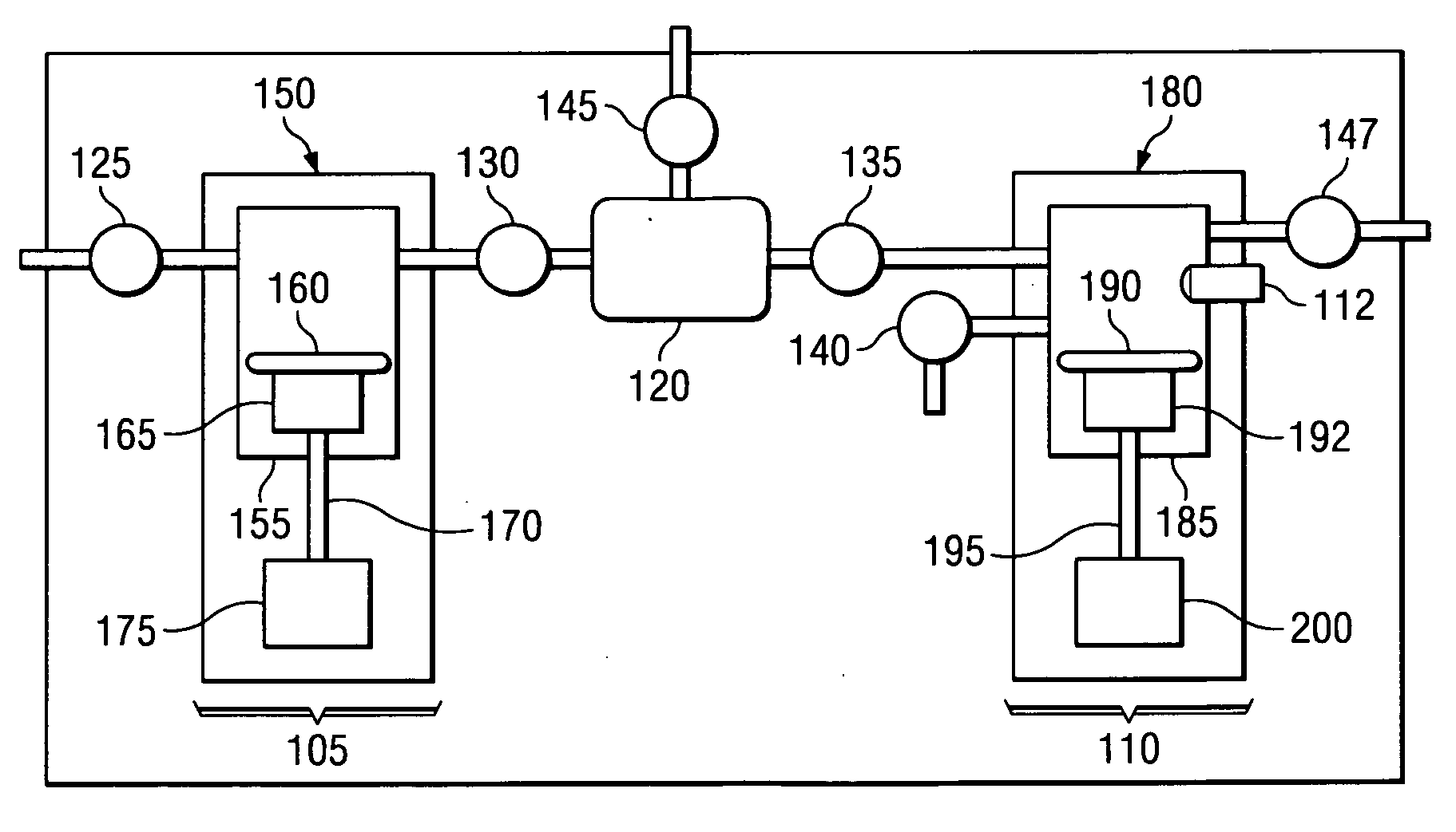
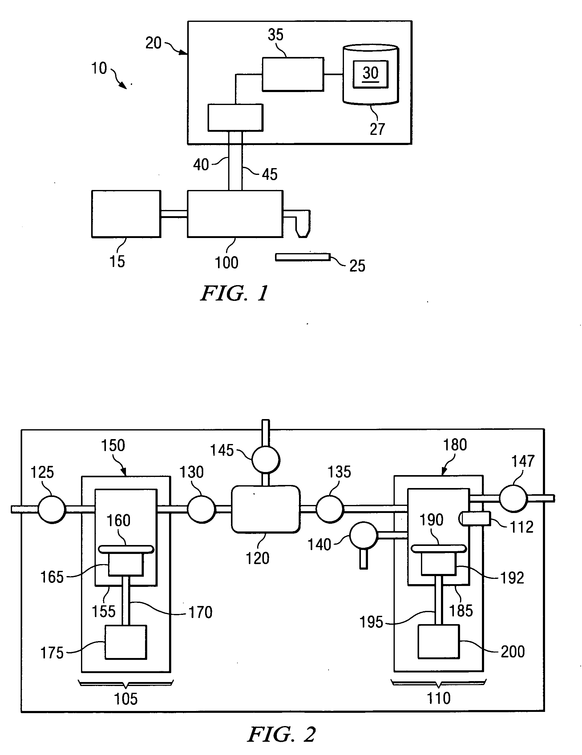
[0044]FIG. 1 is a diagrammatic representation of a pumping system 10. The pumping system 10 can include a fluid source 15, a pump controller 20 and a multi-stage pump 100, which work together to dispense fluid onto a wafer 25. The operation of multi-stage pump 100 can be contr...


PUM

PropertyMeasurementUnit
viscosityaaaaaaaaaa
diameteraaaaaaaaaa
thickaaaaaaaaaa

Abstract

Embodiments of the present invention provide pumps with features to reduce form factor and increase reliability and serviceability. Additionally, embodiments of the present invention provide features for gentle fluid handling characteristics. Embodiments of the present invention can include a pump having a motor driven feed stage pump and a motor driven dispense stage pump. The feed stage motor and the feed stage motor can include various types of motors and the pumps can be rolling diaphragm or other pumps. According to one embodiment, a dispense block defining the pump chambers and various flow passages can be formed out of a single piece of material.

Description

RELATED APPLICATIONS [0001] The present application claims under 35 U.S.C. 120 benefit of and priority to PCT Patent Application No. PCT / US2005 / 042127 entitled “SYSTEM AND METHOD FOR A VARIABLE HOME POSITION DISPENSE SYSTEM” by Applicant Entegris Inc. and inventors Laverdiere et al. filed Nov. 21, 2005 in the United States Receiving Office [Atty. Dkt. No. ENTG1590-WO], and under 35 U.S.C. 119(e) benefit of and priority to U.S. Provisional Patent Application No. 60 / 742,435 entitled “SYSTEM AND METHOD FOR MULTI-STAGE PUMP WITH REDUCED FORM FACTOR” by Cedrone et al., filed Dec. 5, 2005 [Atty. Dkt. No. ENTG1720], both of which are hereby incorporated by reference.TECHNICAL FIELD OF THE INVENTION [0002] This invention relates generally to fluid pumps. More particularly, embodiments of the present invention relate to multi-stage pumps. Even more particularly, embodiments of the present invention relate to a multi-stage pump with reduced form factor. BACKGROUND OF THE INVENTION [0003] Ther...

Claims


Application Information

Patent Timeline
Patent Type & Authority Applications(United States)
IPC IPC(8): F04B3/00
CPCF04B13/00F04B23/06F04B25/00Y10T29/49236F04B49/065F04B43/04F04B43/02F04B53/06F04B53/16F04B53/22Y10T137/87885F04B7/0076F04B9/02F04B53/10F04B2201/0201F04B2201/0601F04B2205/03
Inventor CEDRONE, JAMESGONNELLA, GEORGEGASHGAEE, IRAJ
Owner ENTEGRIS INC
Why Eureka
Try Eureka