Integrated hydrocarbon cracking and product olefin cracking

a technology of hydrocarbon cracking and product olefin, applied in the field of hydrocarbon processing, can solve the problems of general failure of the processing scheme and arrangement in the prior art, and achieve the effect of increasing the yield of c2 and c3

Inactive Publication Date: 2007-06-07
UOP LLC
View PDF14 Cites 2 Cited by
  • Summary
  • Abstract
  • Description
  • Claims
  • Application Information

AI Technical Summary

Benefits of technology

[0007] A more specific objective of the invention is to overcome one or more of the problems described above.

Problems solved by technology

The prior art generally fails to a processing scheme and arrangement that is as effective and efficient in increasing the relative yield of light olefins as may be desired as compared to conventional hydrocarbon cracking processing.

Method used


Image

  • Integrated hydrocarbon cracking and product olefin cracking
  • Integrated hydrocarbon cracking and product olefin cracking

Examples


Embodiment Construction

[0015] A heavy hydrocarbon feedstock can be cracked to produce and process an effluent comprising a range of hydrocarbon products including C4-C7 olefins. At least a portion of such C4-C7 olefins can subsequently be cracked to produce additional C2 and C3 olefins.

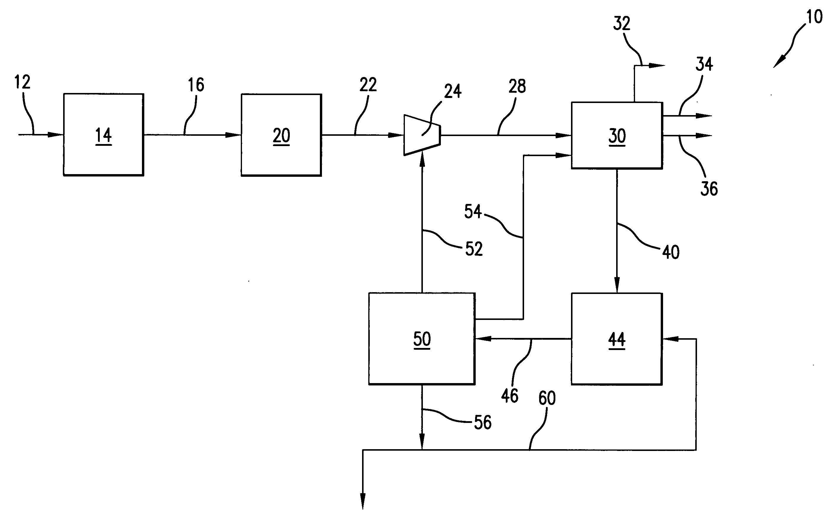
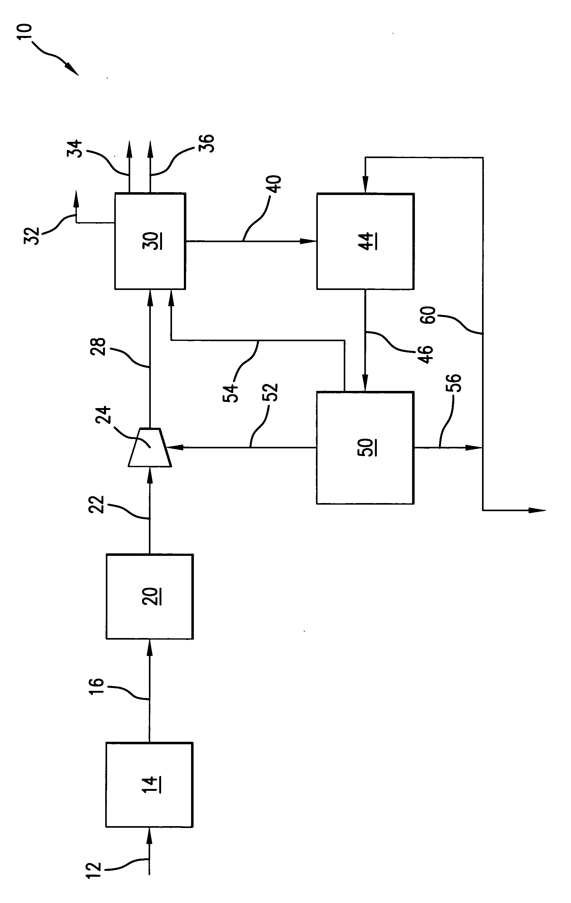
[0016] The FIGURE schematically illustrates a system, generally designated by the reference numeral 10, for the integrated processing of a heavy hydrocarbon feedstock to produce or result in an increased relative amount of light olefins in accordance with one embodiment.

[0017] More particularly, in the system 10, a suitable heavy hydrocarbon feedstock is introduced via a feed line 12 into a fluidized catalytic cracking section 14 wherein the heavy hydrocarbon feedstock contacts with a hydrocarbon cracking catalyst in a primary fluidized bed reactor to produce a hydrocarbon effluent comprising a range of hydrocarbon products including C4-C7 olefins.

[0018] Suitable fluidized catalytic cracking sections for use in the pract...


PUM

PropertyMeasurementUnit
boiling pointaaaaaaaaaa
concentrationaaaaaaaaaa
gas concentrationaaaaaaaaaa

Abstract

Processing scheme and arrangement for increasing the relative yield of light olefins involves integration of the cracking a heavy hydrocarbon feedstock to produce an effluent comprising a range of hydrocarbon products including C4-C7 olefins and the subsequent cracking at least a portion of the C4-C7 olefins to produce additional light olefins.

Description

BACKGROUND OF THE INVENTION [0001] This invention relates generally to hydrocarbon processing and, more particularly, to integrated processing of a heavy hydrocarbon feedstock to increase the yield of light olefins. [0002] Light olefins serve as feed materials for the production of numerous chemicals. Light olefins have traditionally been produced through the processes of steam or catalytic cracking of hydrocarbons such as derived from petroleum sources. Fluidized catalytic cracking (FCC) of heavy hydrocarbon streams is commonly carried out by contacting a starting material whether it be vacuum gas oil, reduced crude, or another source of relatively high boiling hydrocarbons with a catalyst such as composed of finely divided or particulate solid material. The catalyst is transported in a fluid-like manner by transmitting a gas or vapor through the catalyst at sufficient velocity to produce a desired regime of fluid transport. Contact of the oil with the fluidized material catalyzes ...

Claims


Application Information

Patent Timeline
Patent Type & Authority Applications(United States)
IPC IPC(8): C07C2/00C07C4/02B01J8/24
CPCC10G51/04C10G2400/20C10G47/00B01J8/18C10G35/14
Inventor ZIMMERMANN, JOSEPH E.LUEBKE, CHARLES P.BAKER, JOHN B.
Owner UOP LLC
Why Eureka
Try Eureka