
Keyboard apparatus of electronic musical instrument

a musical instrument and keyboard technology, applied in the direction of instruments, measurement devices, speed/acceleration/shock measurement, etc., can solve the problems of few movable parts that are complicatedly correlated to operate, deviation of the weight of the keys contained in a grade, etc., and achieve the effect of uniform reaction for

Active Publication Date: 2007-06-14
YAMAHA CORP
View PDF22 Cites 11 Cited by
  • Summary
  • Abstract
  • Description
  • Claims
  • Application Information

AI Technical Summary

Benefits of technology

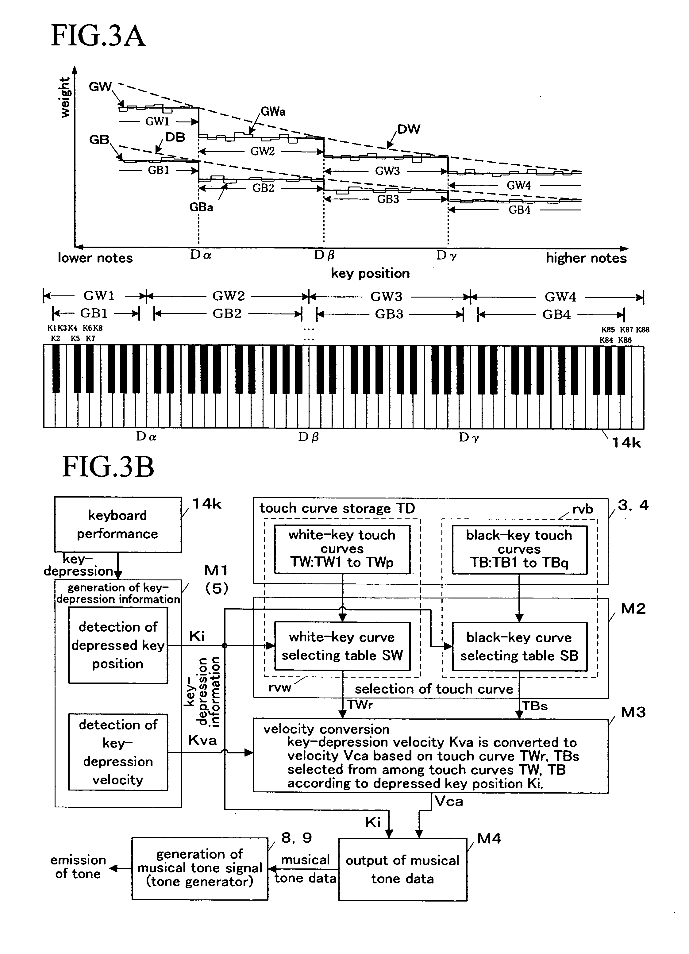
The present invention provides a keyboard apparatus for an electronic musical instrument that can mechanically control the touch response of the keyboard. However, the invention also allows for the software to smoothly equalize any mechanically perceived deviation in the touch response of the keyboard. This is achieved through a velocity generation rule that provides a small velocity for keys with a small key-depression velocity and a large velocity for keys with a larger key-depression velocity. Additionally, the invention includes a touch response correction rule that provides a small velocity for keys with a low reaction force and a large velocity for keys with a high reaction force. This allows for perceptive control of the touch response of the keys without mechanical control of the keys. The invention also separates the velocity generation rule into a white-key rule and a black-key rule to separately control the touch response of the white and black keys.

Problems solved by technology

In either scheme, however, implementation in actual products is difficult due to problems of manufacturability and cost.
In the keyboard mechanism, however, quite a few movable parts are complicatedly correlated to operate.
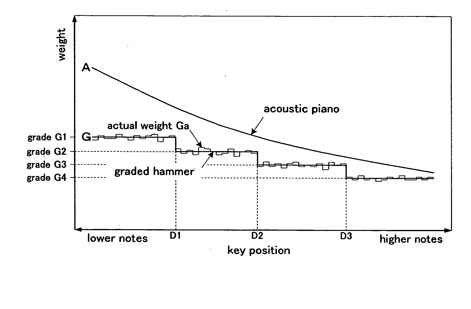
In addition to tolerances of parts, furthermore, the keyboard mechanism also include many slid areas, resulting in deviation of the weight of the keys contained in a grade.
Because the graded hammer mechanism has a limit to the number of mechanically available hammer types, furthermore, connections between the grades each having a hammer of different weight result in steps.
Some players realize the steps, which results in their decreased quality satisfaction.

Method used


Image

  • Keyboard apparatus of electronic musical instrument
  • Keyboard apparatus of electronic musical instrument
  • Keyboard apparatus of electronic musical instrument

Examples


Embodiment Construction

[System Overview]

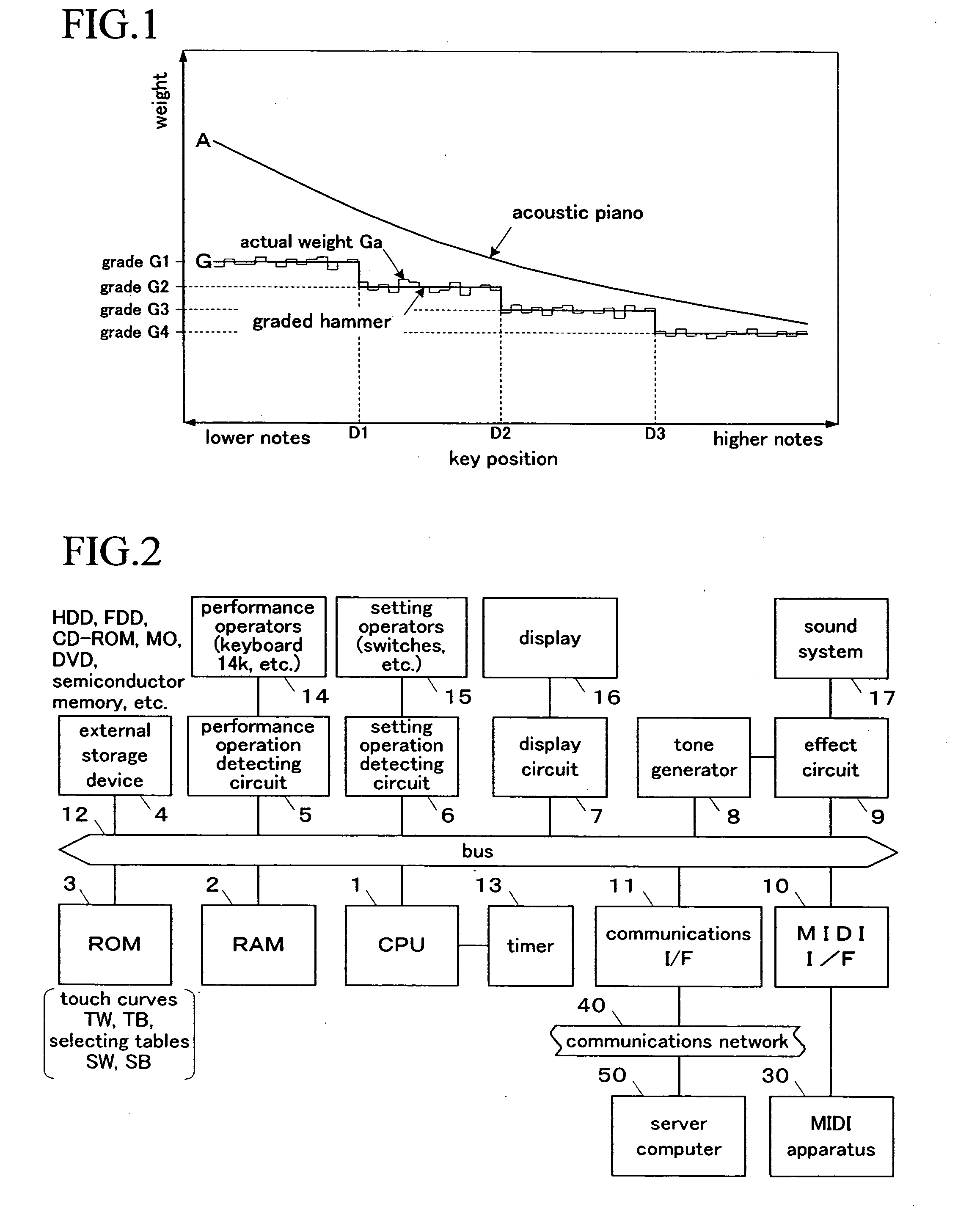
[0038]FIG. 2 is a block diagram showing a hardware configuration of an electronic musical instrument according to an embodiment of the present invention. The electronic musical instrument has a central processing unit (CPU) 1, a random-access memory (RAM) 2, a read-only memory (ROM) 3, an external storage device 4, a performance operation detecting circuit 5, a setting operation detecting circuit 6, a display circuit 7, a tone generator 8, an effect circuit 9, a MIDI interface (I / F) 10, a communications interface (I / F) 11 and the like. These elements 1 through 11 are interconnected through a bus 12.

[0039] On the basis of specified control programs, the CPU 1 executes various music information processes including a touch-control process (also referred to as a touch response providing process or a touch response correcting process) through the use of a clock operated by a timer 13. The RAM 2 is used as a working area for temporarily storing various kinds of data nec...


PUM


Abstract

A keyboard apparatus of this electronic musical instrument is provided with touch curves TW1 through TWp, TB1 through TBq each defining a velocity value Vc varying with a key-depression velocity Kv (TD). Each of keys K1 through Kn of a keyboard 14k is associated with one of the touch curves TW1 through Twp, TB1 through TBq by touch selecting tables SW, SB in accordance with an equalization rule and a weighting rule. Upon a key-depression, in accordance with the velocity curve TWr, TBs selected on the basis of an actual depressed key position Ki (M2), an actual key-depression velocity Kva is converted into a velocity Vca for controlling emission of a tone (M3).

Description

BACKGROUND OF THE INVENTION [0001] 1. Field of the Invention [0002] The present invention relates to a keyboard apparatus of an electronic musical instrument designed such that the touch response is controlled by way of software. [0003] 2. Description of the Related Art [0004] In a conventional keyboard apparatus of an electronic musical instrument, as described in Japanese Patent Laid-Open Publication No. H09-6329, for example, each key is provided with its corresponding mass element referred to as a “hammer” so that a force corresponding to the movement of the mass element brought by a key-depression is yielded as the reaction to the force exerted at the key-depression. As a result, the conventional keyboard apparatus achieves desired touch response having weight which is close to the touch response of the key-depressions of an acoustic musical instrument. [0005]FIG. 1 shows weight characteristics of respective keys of a case in which the touch response of key-depression is mechan...

Claims


Application Information

Patent Timeline
Patent Type & Authority Applications(United States)
IPC IPC(8): G01P3/00G10H5/00
CPCG10H1/057G10H1/46
Inventor NISHIDA, KENICHITAMAZAWA, YASUSHI
Owner YAMAHA CORP
Learn More