Fuel injector

a fuel injector and fuel line technology, applied in the direction of liquid fuel feeders, machines/engines, mechanical equipment, etc., can solve the problems of unavoidable flexibility, high cost, and inability to meet the requirements of the cylinder head, and achieve simple and hydraulically advantageous manner, simple and reliable manner, and simple interconnection of fuel lines

Inactive Publication Date: 2007-06-14
ROBERT BOSCH GMBH
View PDF6 Cites 2 Cited by
  • Summary
  • Abstract
  • Description
  • Claims
  • Application Information

AI Technical Summary

Benefits of technology

[0004] A fuel-injection system according to an example embodiment of the present invention may have the advantage that the required space, installation expense and the susceptibility to faults are considerably reduced. Moreover, the fuel-injection system may be very resistant to mechanical external influences. In addition, the number of detachable and fault-susceptible high-pressure connections may be markedly reduced.
[0005] In a preferred exemplary embodiment of the fuel-injection system according to the present invention the fuel connection of the fuel injector is arranged at the level of the valve needle. This allows for a very simple design of the fuel injector. In particular, it is possible to dispense with extensive sealing of the actuator chamber or the actuator and to use smaller dimensions for the fuel injector. This considerably reduces the installation space of the fuel injector in the cylinder head and improves the stability of the cylinder head.
[0006] The fuel lines may also be connected via at least the valve receiving openings and / or the fuel connections. In this way an especially simple interconnection of the fuel lines is possible.

Problems solved by technology

In particular when using this system in internal combustion engines having fuel injectors of a simpler construction and high-pressure injection without integrated pump, a disadvantage is that the fuel lines located outside the cylinder head will have been produced in a very complex manner and may be costly due to their unavoidable flexibility.

Method used


Image

  • Fuel injector
  • Fuel injector
  • Fuel injector

Examples


Embodiment Construction

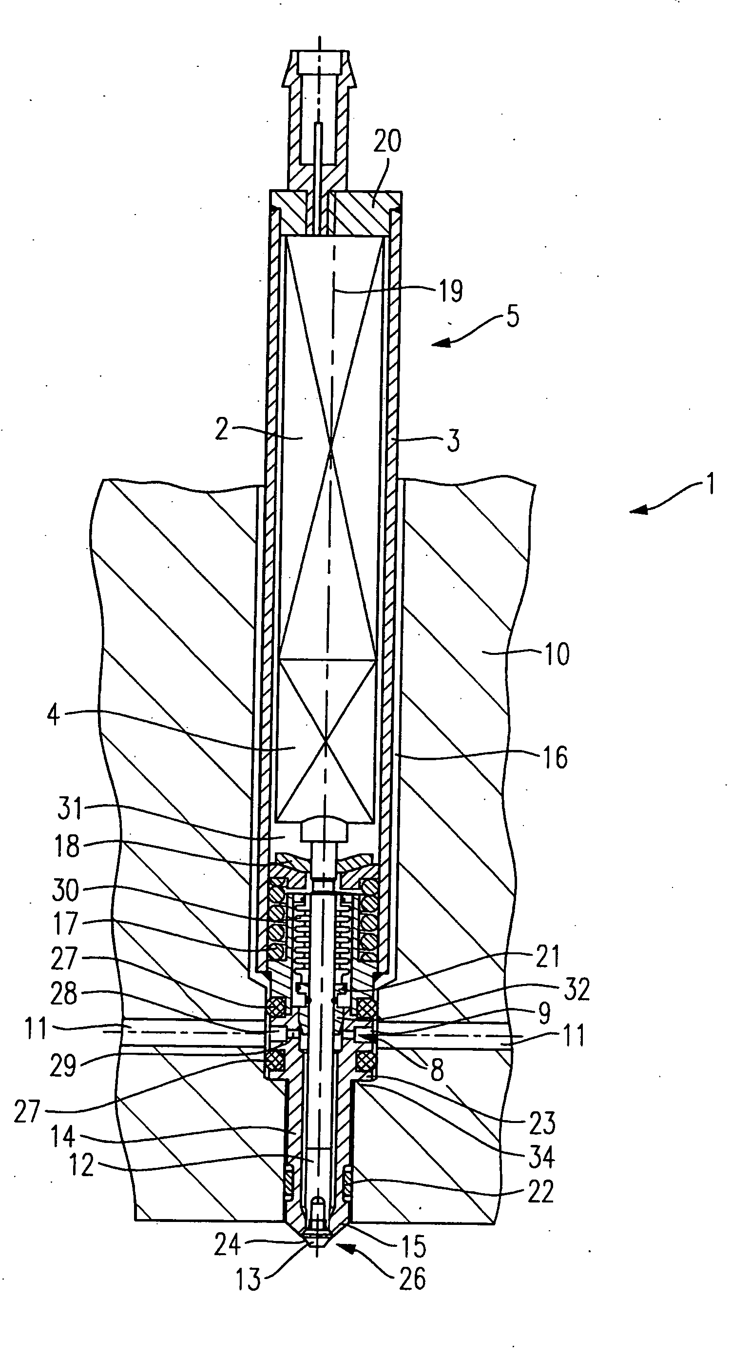
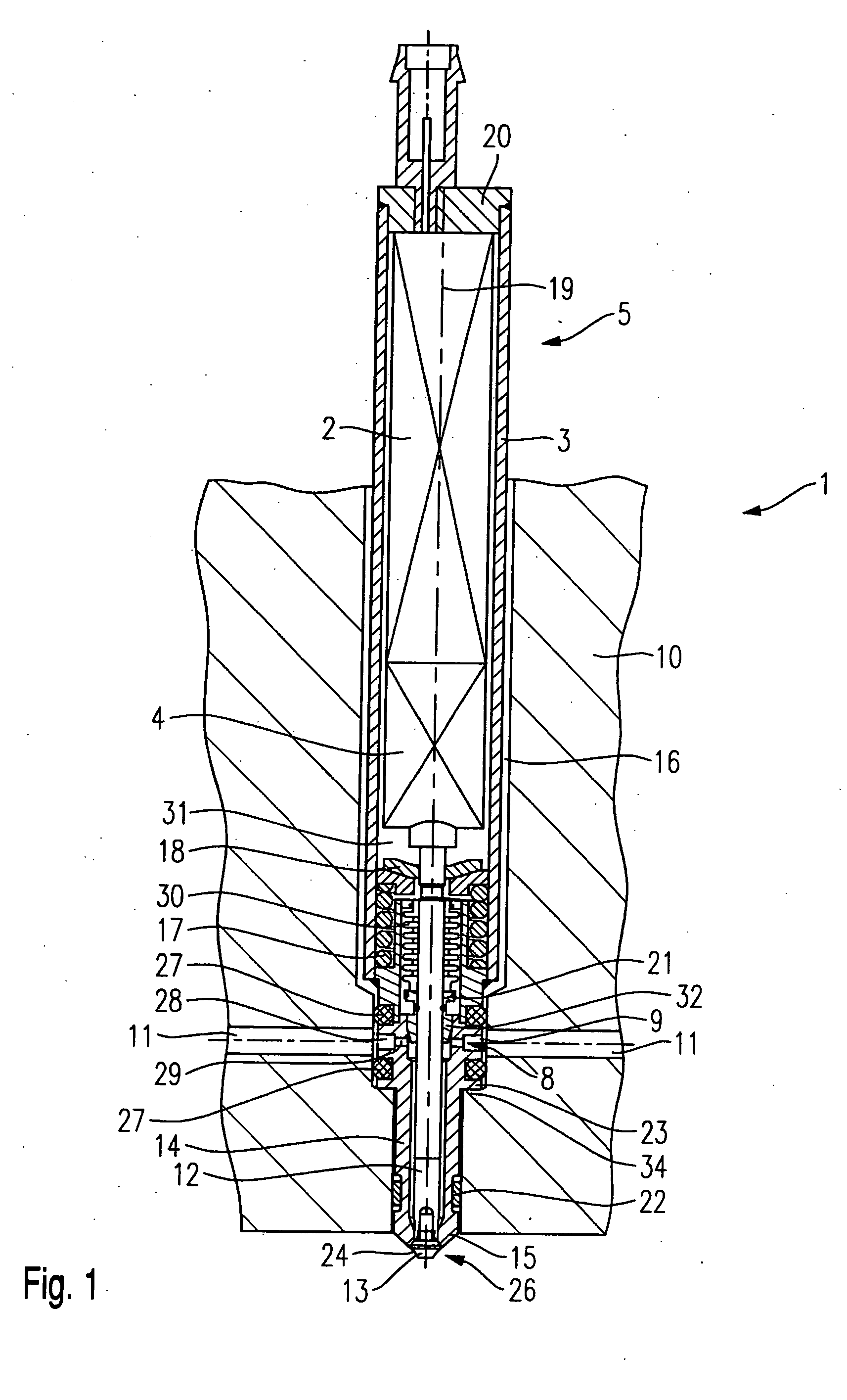
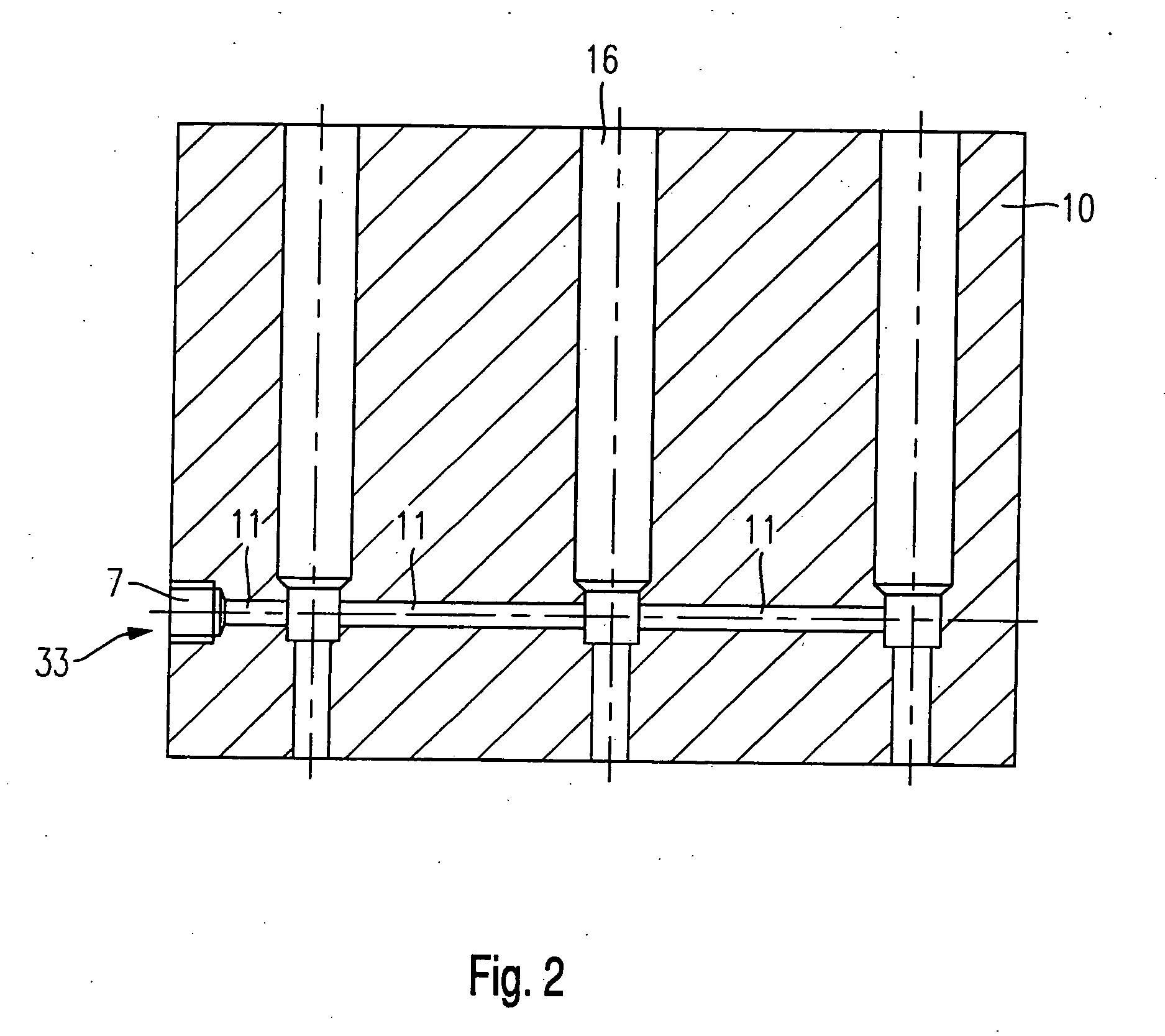
[0015] Fuel-injection system 1 shown in FIG. 1 is generally made up of a fuel injector 5 which is suitable as fuel injector 5 for fuel-injection systems of mixture-compressing internal combustion engines having external ignition for the direct injection of fuel into the combustion chamber of the internal combustion engine, and a cylinder head 10, which is shown only in part and has fuel lines 11 extending therein, which are interconnected inside cylinder head 10.

[0016] Fuel injector 5 engages with a cylindrical valve receiving opening 16, which is positioned in cylinder head 10, extends in the direction of the combustion chamber (not shown) and has a tapered design. In this exemplary embodiment, fuel injector 5 projects into the combustion chamber through valve-receiving opening 16 via its discharge-side end.

[0017] Fuel injector 5 is generally made up of a circular-cylindrical housing 3, which is sealed by a top 20 on the discharge-remote side, a nozzle body 14, an actuator 2 such...


PUM


Abstract

A sensor is used to sense a property relating to each one of a plurality of different elevational locations within a vertical plane that is normal to a length of an aircraft. The vertical plane passes through the doorway of the aircraft, and at least some of the plurality of different elevational locations are disposed outside a known surface boundary of the aircraft. A variation in the sensed property between two elevational locations is detected, the variation indicative of an elevational position of the known surface boundary. An elevational position of the doorway of the aircraft is determined based upon a known relationship between the known surface boundary and the doorway, and based upon the indicated elevational position of the known surface boundary. The determined elevational position of the doorway is used to guide an aircraft engaging portion of the movable bridge into elevational alignment with the said doorway.

Description

FIELD OF THE INVENTION [0001] The present invention relates to a fuel injector. BACKGROUND INFORMATION [0002] German Patent Application No. DE 197 12 921 A1 describes a fuel-injection system which includes a cylinder head and at least one fuel injector having piezoelectric actuation. A fuel-supply line through which fuel flows into the individual fuel injector under relatively low pressure (3 to 4 bar) on the side, below the actuator, is provided in the cylinder head. Because of the actuator lifts and the action of a piston pump integrated in the fuel injector in the discharge-side region, the fuel is injected into the combustion chamber under a much higher pressure. [0003] In particular when using this system in internal combustion engines having fuel injectors of a simpler construction and high-pressure injection without integrated pump, a disadvantage is that the fuel lines located outside the cylinder head will have been produced in a very complex manner and may be costly due to...

Claims


Application Information

Patent Timeline
Patent Type & Authority Applications(United States)
IPC IPC(8): F02M55/02F02F1/24F02F1/40F02M55/00F02M61/08F02M61/14F02M61/16
CPCF02F1/242F02M55/00F02M61/08F02M61/14F02M61/165
Inventor WOLFF, GUENTERSTRAUSS, BERNDSTIER, HUBERTGOLLER, HELGANUESSLEIN, STEFANBRENDEL, REINHARD
Owner ROBERT BOSCH GMBH
Why Eureka
Try Eureka