Heat dissipating module and method of fabricating the same

Inactive Publication Date: 2007-06-14
AMA PRECISION INC
View PDF7 Cites 12 Cited by
  • Summary
  • Abstract
  • Description
  • Claims
  • Application Information

AI Technical Summary

Problems solved by technology

However, the structure assembled in the manner mentioned above is not compact enough, such that the fins could loose from the thermal conductive pipe or deform during deliever.
Thus, the contact area of the thermal conductive pipes with the fins of the thermal fin module is reduced, so that the heat dissipating effect is not good.

Method used


Image

  • Heat dissipating module and method of fabricating the same
  • Heat dissipating module and method of fabricating the same
  • Heat dissipating module and method of fabricating the same

Examples


Embodiment Construction

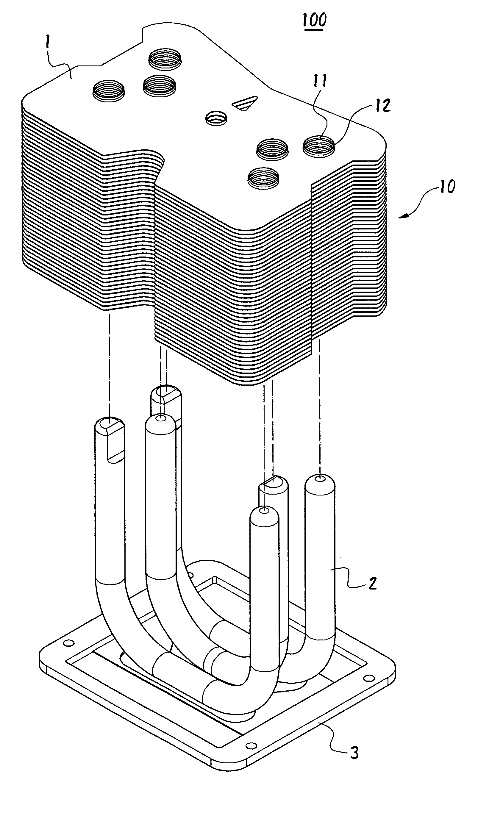
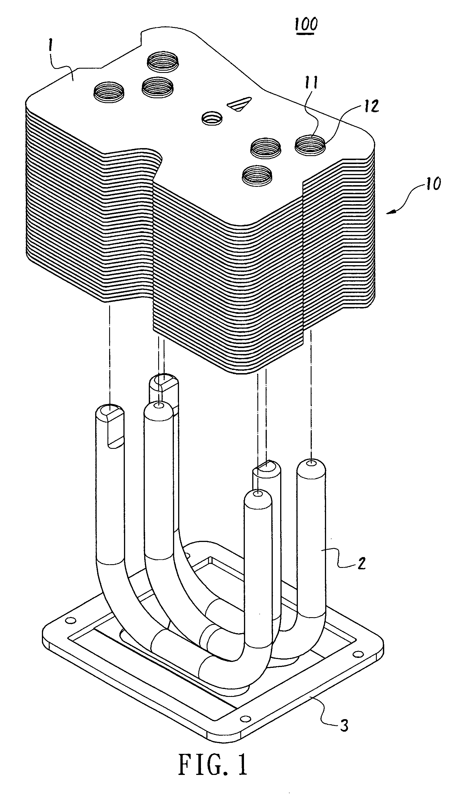
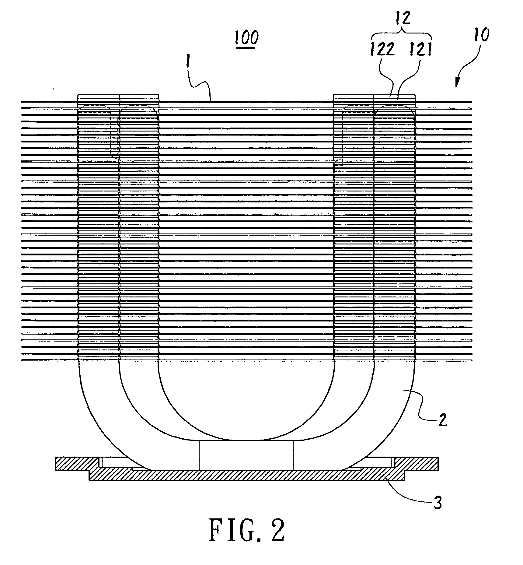
[0022] Please refer to FIGS. 1-13. According to the present invention, a method of fabricating a heat dissipating device comprises the following steps:

[0023] a) mounting a thermal fin module 10 made by pressing and stacking a plurality of fins 1 on thermal conductive pipes 2;

[0024] b) setting a jig 20 on the top surface of the thermal fin module 10, and compressing downward the thermal fin module 10;

[0025] c) mounting a fixing plate 4 above the thermal fin module 10 on the thermal conductive pipes 2, and removing the jig 20; and

[0026] d) setting the fixing plate 4 on the thermal fin module 10 to make the thermal fin module 10 securely fixed on the thermal conductive pipes 2.

[0027] In FIG. 1, the thermal conductive pipes 2 pass through the fins 1 with a thickness of less than 0.2 mm. The fins 1 are used to dissipate heat from the thermal conductive pipes 2. The fins 1 and the thermal conductive pipes 2 are tightly connected, so as to reduce any gap between the fins 1 and the the...


PUM


Abstract

A heat dissipating module includes thermal conductive pipes and a thermal fin module. The thermal fin module made by pressing and stacking is mounted on the thermal conductive pipes. Next, a jig is set on a top surface of the thermal fin module, and a force compresses the thermal fin module, so as to reduce a distance between two fins of the thermal fin module. Then, a fixing plate is set above the thermal fin module on the thermal conductive pipes, and the jig is removed. Finally, the fixing plate is fixed on the thermal fin module, and the thermal fin module is securely fixed with the thermal conductive pipes. Therefore, the assembled heat dissipating module could not be loosed and deformed during delivery and the engaging contact between the fins and the thermal conductive pipes are enhanced, so to increase the heat dissipating effect of the heat dissipating module.

Description

BACKGROUND OF THE INVENTION [0001] 1. Field of the Invention [0002] The present invention relates to a heat dissipating module and a method of fabricating the same, and particularly relates to a method of fabricating a heat dissipating module with a thermal fin module capable of being stably fixed on thermal conductive pipes. [0003] 2. Description of Related Art [0004] Usually, in order to increase the heat dissipating speed, a thermal conductive pipe is passed through the fins of a thermal fin module. Therefore, the heat generated from a heat source could be dissipated through the thermal conductive pipe and the thermal fin module. [0005] During assembling a heat dissipating module, first, a plurality of fins are pressed and stacked together to make the thermal fin module and through holes are correspondingly formed on the fins of the thermal fin module. Then, annular walls are respectively formed surrounding the through holes, and the thermal conductive pipes are passed through th...

Claims


Application Information

Patent Timeline
IPC IPC(8): H05K7/20F28D15/00
CPCF28D15/0233F28D15/0266F28F1/32H01L23/3672H01L23/427H01L2924/0002H01L23/467H01L2924/00F28D15/0275
Inventor CHEN, KUO-HSINLIN, HSUAN-CHIH
Owner AMA PRECISION INC
Why Eureka
Try Eureka