Retainer and one-way clutch using the retainer and method for assembling the one-way clutch

a one-way clutch and retainer technology, which is applied in the field of retainer and one-way clutch using retainer, can solve the problems of increasing the assembling cost the man-hours required for the assembly of the one-way clutch, and achieves the effects of low cost, simple assembly and low cos

Inactive Publication Date: 2007-06-14
JTEKT CORP
View PDF7 Cites 2 Cited by
  • Summary
  • Abstract
  • Description
  • Claims
  • Application Information

AI Technical Summary

Benefits of technology

[0060] In the retainer of one embodiment, since the non-engagement outer peripheral surface is a cylindrical surface, the non-engagement outer peripheral surface can be machined with simplicity, so that the retainer can be manufactured with low cost.
[0061] According to the retainer of the second aspect of the invention, a non-engagement inner peripheral surface positioned outside a circle larger by a specified size than the circumcircle of the engagement portions is provided on the inner peripheral surface of the other annular portion and part of each of the pillar portions positioned on the annular portion side. Therefore, part of the rollers of the retainer assembly wherein the retainer assembly is formed by setting the rollers and the biasing member in the retainer can be inserted beforehand at clearance-fit positions between the inner peripheral surface of the outer ring and the outer peripheral engagement surface of the inner ring before making the engagement portion of the retainer and the engagement portion of the inner ring coincident with each other in peripheral position and inserting the retainer assembly to between the inner peripheral surface of the outer ring and the outer peripheral engagement surface of the inner ring of the one-way clutch. Therefore, because there is no need for moving the rollers located near wedge positions to near the clearance-fit positions by using some exclusive-use equipment, which would be needed in the one-way clutch assembling method using conventional retainers, the one-way clutch can be assembled with simplicity and low cost.
[0062] In the retainer of one embodiment, since the non-engagement inner peripheral surface is a cylindrical surface, the non-engagement inner peripheral surface can be machined with simplicity, so that the retainer can be manufactured with low cost.
[0063] According to the one-way clutch of the first aspect of the invention, since the retainer of the first aspect of the invention is included, the retainer assembly can be inserted to between the inner peripheral engagement surface of the outer ring and the outer peripheral surface of the inner ring with simplicity without using any exclusive-use equipment. Thus, the one-way clutch can be assembled with simplicity and low cost.
[0064] Further, according to the one-way clutch of the second aspect of the invention, since the retainer of the second aspect of the invention is included, the retainer assembly can be inserted to between the inner peripheral surface of the outer ring and the outer peripheral engagement surface of the inner ring with simplicity without using any exclusive-use equipment. Thus, the one-way clutch can be assembled with simplicity and low cost.
[0065] Further, according to the method for assembling the one-way clutch of the first and second aspects of the invention, the one-way clutch can be assembled with simplicity and low cost without using any exclusive-use equipment.

Problems solved by technology

However, with the use of the prior art retainer shown in FIG. 6, there is a problem that the assembling of the one-way clutch involves the need for exclusive-use equipment for moving the roller, which is present at a position in phase with an engagement position where the radial distance between outer and inner rings is narrower than the diameter of the roller, up to a position in phase with a clearance-fit position.
Also, because of a need for setting the outer ring, the inner ring and the retainer assembly to the exclusive-use equipment, there is another problem that man-hours required for the assembling of the one-way clutch is increased, which leads to an increase in the assembling cost of the one-way clutch.

Method used


Image

  • Retainer and one-way clutch using the retainer and method for assembling the one-way clutch
  • Retainer and one-way clutch using the retainer and method for assembling the one-way clutch
  • Retainer and one-way clutch using the retainer and method for assembling the one-way clutch

Examples


Embodiment Construction

[0072] Hereinbelow, the present invention will be described in detail by embodiments thereof illustrated in the accompanying drawings.

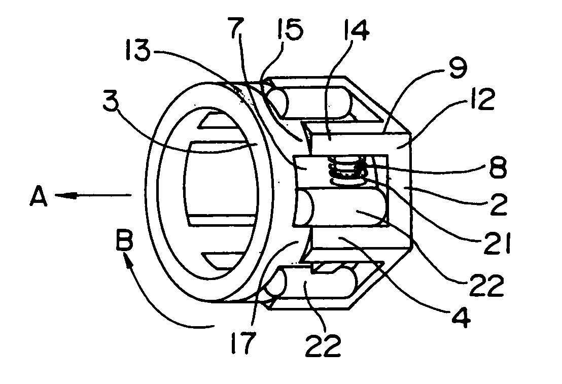
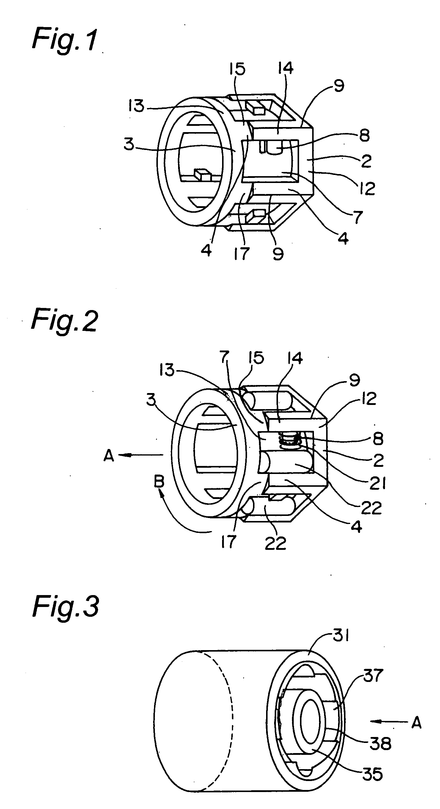
[0073]FIG. 1 shows a retainer for use with a one-way clutch according to an embodiment of the retainer in a first aspect of the invention. The retainer includes an annular portion 2, an annular portion 3 confronting the annular portion 2, and six pillar portions 4 for connecting the annular portion 2 and the annular portion 3 to each other. Six pockets 7 are formed between the six pillar portions 4. It is noted that reference numeral 8 denotes a protruding portion to which an unshown coil spring as an example of biasing member is to be fitted.

[0074] The annular portion 2 has an outer peripheral surface 12 having a generally regular hexagonal shape in its cross section and a cylindrical inner peripheral surface. The annular portion 3 has an outer circumferential cylindrical surface 13 smaller in radial size than a circumcircle of edges 9 of the outer...


PUM

PropertyMeasurementUnit
sizeaaaaaaaaaa
shapeaaaaaaaaaa
radial distanceaaaaaaaaaa

Abstract

An outer peripheral cylindrical surface 13, 17, which is a non-engagement outer peripheral surface, is formed in an outer periphery of an annular portion 3 and a portion 15 of each of pillar portions 4, while an engagement portion formed of an edge 9 is formed on an outer periphery of the other annular portion 2 and another portion 14 of each of the pillar portions 4. The outer peripheral cylindrical surface 13, 17 is formed inside a circle smaller by a specified size than a circumcircle of the edges 9.

Description

BACKGROUND OF THE INVENTION [0001] The present invention relates to a retainer and a one-way clutch using the retainer as well as to a method for assembling the one-way clutch. [0002] Conventionally, there has been a retainer shown in FIG. 6 for use in one-way clutches. This retainer has a first annular portion 81, a second annular portion 82 confronting the first annular portion 81, and six pillar portions 85 for connecting the first annular portion 81 and the second annular portion 82 to each other. Then, six pockets 87 are formed between the six pillar portions 85. It is noted that reference numeral 92 denotes a protruding portion to which an unshown coil spring is to be fitted. [0003] Outer peripheral surfaces of the first and second annular portions 81, 82 are formed into an identical generally regular hexagonal shape. The pillar portions 85 are formed by axially extending six edges of the outer peripheral surface of the first annular portion 81 and six edges of the outer perip...

Claims


Application Information

Patent Timeline
Patent Type & Authority Applications(United States)
IPC IPC(8): F16D41/06F16D41/067
CPCY10T29/49904F16D41/067
Inventor WATANABE, HAJIME
Owner JTEKT CORP
Why Eureka
Try Eureka