Octagonal bulk bin with self-locking webbed bottom flaps

a technology of bottom flap and octagonal bin, which is applied in the field of self-locking bottom flap construction of octagonal bulk bin, can solve the problems of bin failure, sidewall bursting, tearing of vertical fold, etc., and achieves the effects of reducing or eliminating contamination problems, facilitating the setup of octagonal bins, and facilitating application

Active Publication Date: 2007-06-14
INT PAPER CO
View PDF11 Cites 17 Cited by
  • Summary
  • Abstract
  • Description
  • Claims
  • Application Information

AI Technical Summary

Benefits of technology

[0010] The present invention comprises a bulk bin with self-locking bottom flaps constructed so that the bin is relatively easy to erect, and which avoids the formation of weak points where tearing of the vertical fold can initiate, and avoids the formation of pinch points in the bottom.
[0011] The bulk bin of the invention is an octagonal bin, erected from a single unitary blank, with opposed sidewalls, end walls, and diagonal corner walls or panels interposed between adjacent side and end walls, said walls being connected together along vertical folds at their adjacent side edges. The sidewalls generally have a greater width than the end walls, and in a preferred embodiment the end walls and diagonal walls have the same width, thus reducing the width of the sidewalls and end walls in a bin having a comparable capacity, and thereby reducing outward bulge of the sidewalls and / or end walls, although the invention has equal applicability in a bin having diagonal walls that are narrower than the end walls. A major bottom flap is foldably joined to the bottom edge of each sidewall, a minor bottom flap is foldably joined to the bottom edge of each end wall, and a diagonal bottom flap is foldably joined to the bottom edge of each diagonal wall, said flaps being foldably joined to the respective walls along horizontal folds substantially perpendicular to the vertical folds. The major and minor flaps typically have the same width (as used herein with reference to the flaps, “width” refers to the distance between the free edge of the flap and its folded connection with a respective wall), but the width of the diagonal flaps is substantially less. The major flaps have generally trapezoidally shaped extensions projecting from their opposite side edges and these extensions are separated from adjacent diagonal flaps by angled cuts extending from an outer edge of a respective diagonal flap to a point near the juncture of an adjacent vertical fold and the horizontal fold for that major flap. Material is cut from between adjacent side edges of the major and minor flaps in the area located beyond the free edge of an associated diagonal flap so that these edges are spaced from one another.

Problems solved by technology

This structure creates a weak point where tearing of the vertical fold can initiate.
Tearing of the vertical fold can propagate rapidly upwardly, resulting in bursting of the sidewall and failure of the bin, with consequent loss of the stored product.
Conventional octagonal bulk bins with or without self-locking bottom flaps are cumbersome to assemble, and as a result users often seek alternative packaging.
Further, the sequence of inward folding of the bottom flaps on a conventional octagonal bulk bin frequently results in creating extra pinch points in the bottom of the bin, e.g., by the diagonal flaps extending into the interior of the box bottom, which can damage the bag and cause it to rupture, thus contaminating the stored product.

Method used


Image

  • Octagonal bulk bin with self-locking webbed bottom flaps
  • Octagonal bulk bin with self-locking webbed bottom flaps
  • Octagonal bulk bin with self-locking webbed bottom flaps

Examples


embodiment 80

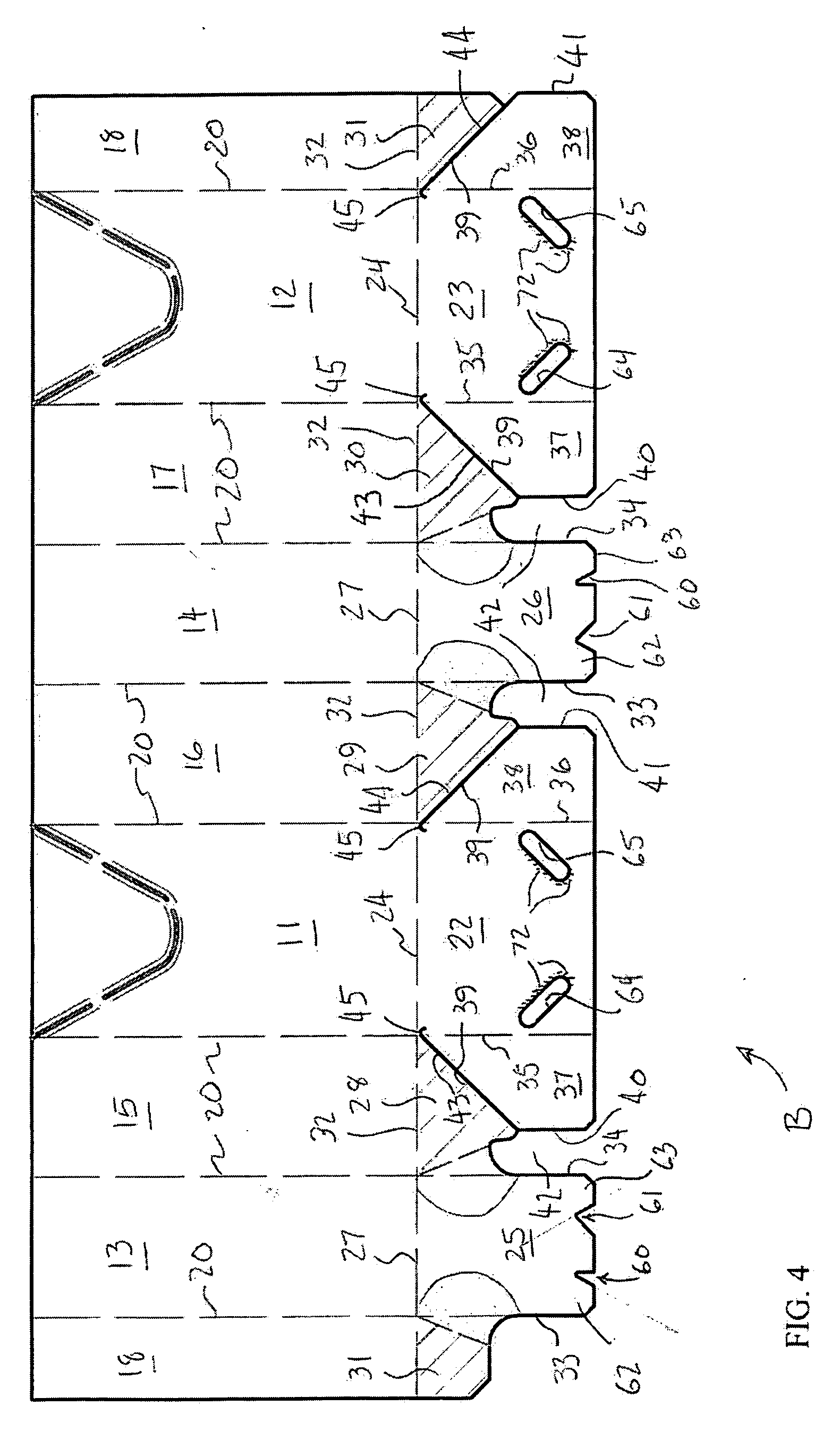
[0050]FIGS. 12 and 13 show another embodiment 80, in which the bottom flaps 22′, 23′, 25′, 26′ and 28′-31′ are not as wide as in the previous embodiment and the major bottom flaps 22′ and 23′ are not intended to overlap, but instead butt against one another at their free edges when they are in their inwardly folded horizontal positions. This form of the invention is identical to the previous form, except that both notches 81 and 82 in the free edge of the minor flaps are identical to one another, and except for the difference in width of the bottom flaps. Thus, the edge 83 of both notches extends substantially perpendicular to the free edge of the flap, and the shoulders 84 and 85 are spaced equally from the center of the flap, whereby the shoulders act to exert substantially equal downward pressure on the major flaps when the box is being set up, and provide substantially equal clearance for return of the major flaps to an upper, horizontal position when pressure is released.

[0051]...

embodiment 110

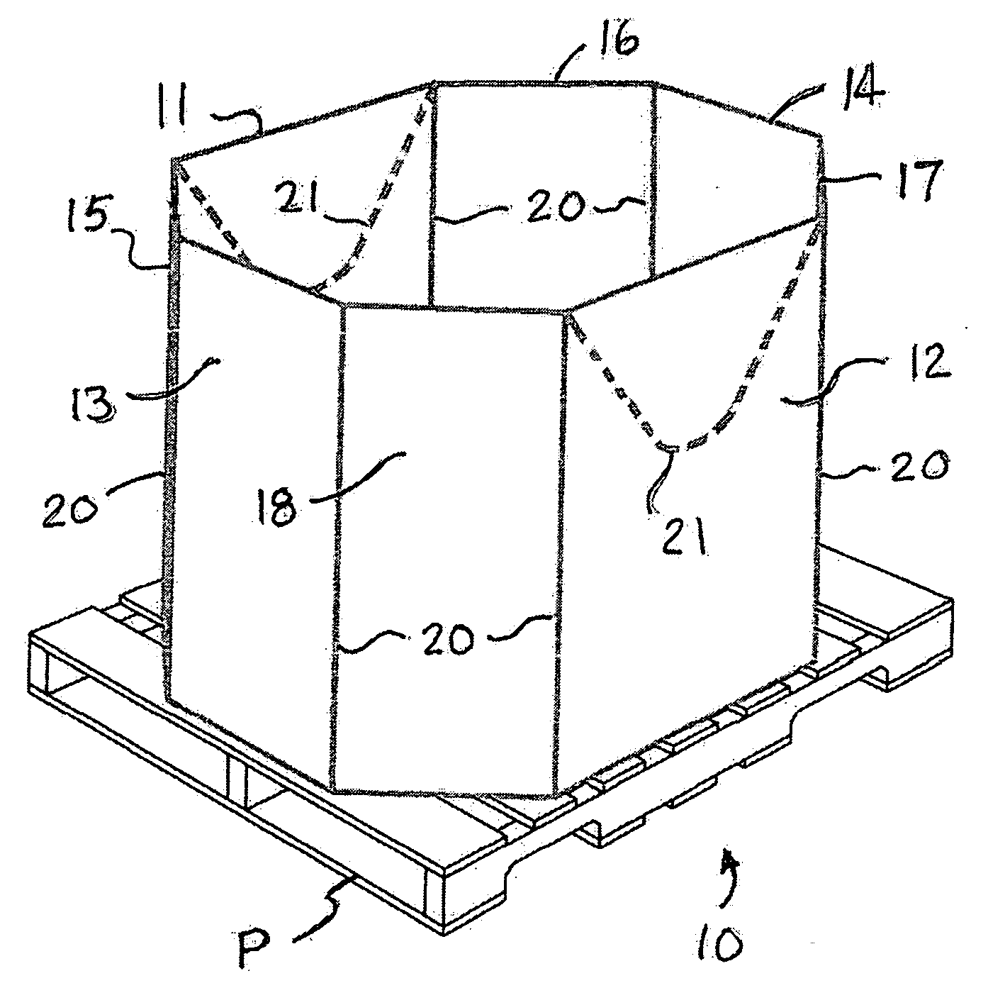
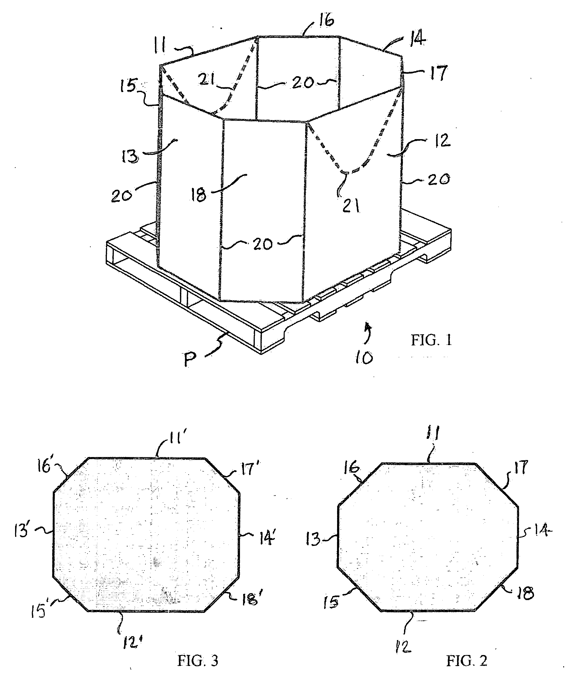
[0053]FIG. 17 shows an embodiment 110 in which the end wall panels 13′ and 14′ have a greater width than the diagonal corner panels 15′-18′. In all other respects, except for differences in the side-to-side dimensions of the bottom flaps resulting from differences in the sidewall, end wall and diagonal corner panel widths, this form of the invention is identical to the form shown in FIG. 4. Also shown in this figure is reinforcing tape 111, which can be applied, or not, to any of the forms of the invention.

[0054] To erect the bin, and with reference to that form shown in FIG. 4, it is placed in an inverted position with its bottom end up as seen in FIGS. 7-10. If desired, to aid in squaring up the bin and to prevent contamination of the top end of the bin, the inverted bin may be placed on a plastic pallet (not shown) as described in U.S. provisional application Ser. No. 60 / 712,236. The major bottom flaps 22 and 23 are first folded inwardly as seen in FIG. 7, followed by inward fold...


PUM


Abstract

An octagonal bulk bin has sidewalls, end walls and diagonal corner panels interposed between adjacent sidewalls and end walls. Major bottom flaps are foldably joined to a bottom edge of the sidewalls, minor bottom flaps are foldably joined to a bottom edge of the end walls, and diagonal bottom flaps are foldably joined to a bottom edge of the diagonal corner panels. A cut separates each major bottom flap from an adjacent diagonal bottom flap, and a web panel connects adjacent side edges of the minor bottom flaps and diagonal bottom flaps. According to one aspect of the invention, each diagonal bottom flap, web panel, and portion of an adjacent major bottom flap are crushed. According to another aspect of the invention, differently shaped notches in a free edge of the minor flaps form locking tabs that are engaged in slots near a free edge of the major flaps.

Description

[0001] This application claims the benefit of U.S. provisional patent application Ser. No. 60 / 712,236, filed Aug. 29, 2005, the entire disclosure of which is incorporated herein by reference.BACKGROUND OF THE INVENTION [0002] 1. Field of the Invention [0003] This invention relates to bulk bins, and particularly to a self-locking bottom flap construction for octagonal bulk bins. [0004] 2. The Prior Art [0005] Bulk bins are used in the industry for storing and shipping numerous products, and typically hold 2,000 pounds or more of the product, including flowable or semi-liquid products such as, e.g., comminuted poultry. When flowable products are to be contained in the bin, a bag normally is placed in the bin for receiving the product. The outward force exerted on the sidewalls by flowable products, in particular, is substantial, and tends to bulge the sidewalls outwardly. The bins are commonly made of corrugated cardboard and comprise a plurality of sidewalls joined together along ver...

Claims


Application Information

Patent Timeline
Patent Type & Authority Applications(United States)
IPC IPC(8): B65D5/10
CPCB65D5/029B65D5/06B65D5/10B65D5/4266B65D15/22B65D19/004B65D2519/00034B65D2519/00069B65D2519/00159B65D2519/00268B65D2519/00815B65D2519/00835Y10S229/93Y10S229/92Y10S229/931
Inventor QUAINTANCE, BENJAMINWISECARVER, MARK
Owner INT PAPER CO
Why Eureka
Try Eureka