Wind energy installation comprising conductor rails

a conductor rail and wind energy technology, applied in the direction of liquid fuel engines, vessel construction, marine propulsion, etc., can solve the problems of costly process, and achieve the effect of convenient, economic and fast installation

Inactive Publication Date: 2006-10-19
WOBBEN ALOYS
View PDF56 Cites 20 Cited by
  • Summary
  • Abstract
  • Description
  • Claims
  • Application Information

AI Technical Summary

Benefits of technology

[0007] The present invention provides a wind-power system, which can be erected more easily and thus also more economically and more quickly, and in which the power module is not absolutely necessarily in the region of the tower base.

Problems solved by technology

This is a costly process, because the cables must be installed in a separate procedure over the entire height of the tower.

Method used


Image

  • Wind energy installation comprising conductor rails
  • Wind energy installation comprising conductor rails
  • Wind energy installation comprising conductor rails

Examples


Embodiment Construction

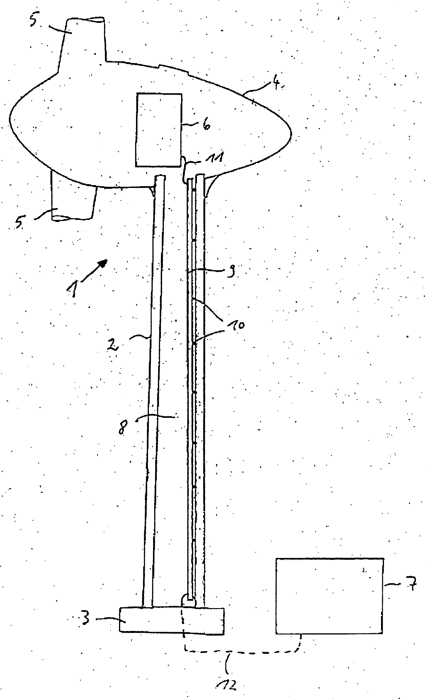
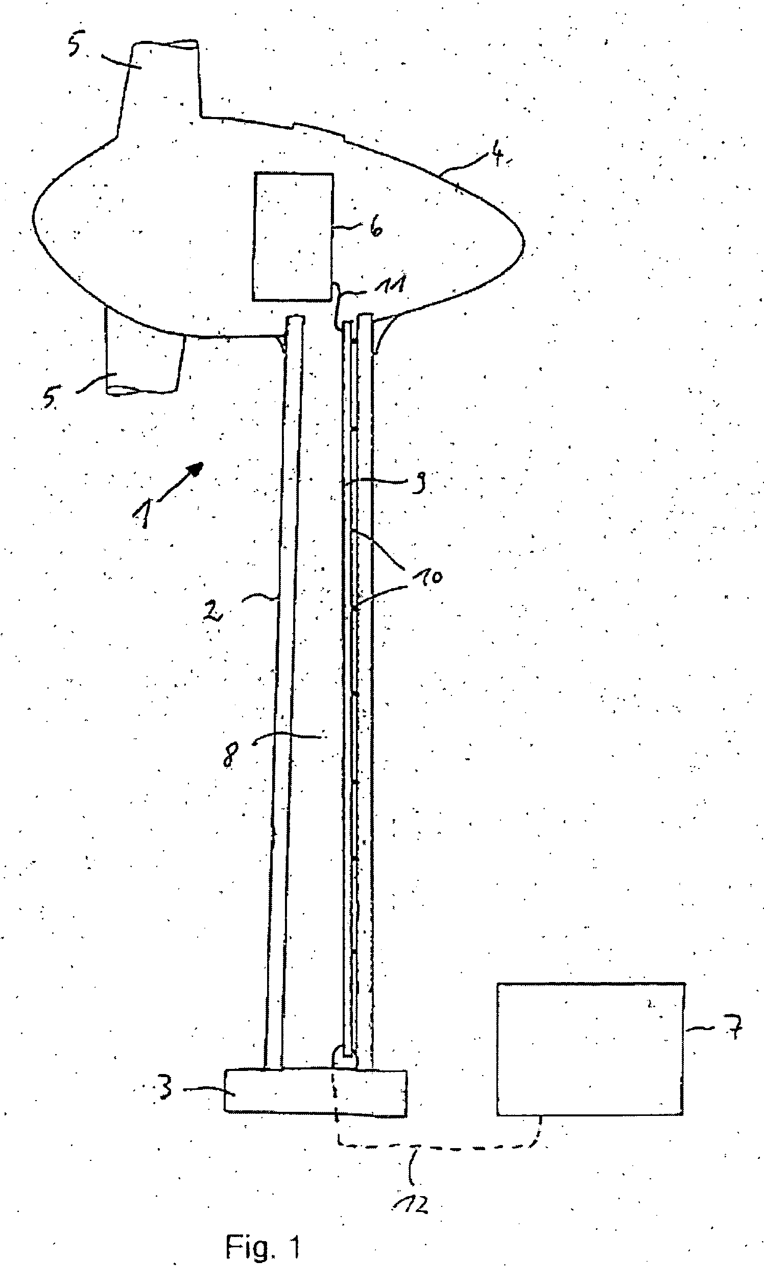
[0026] The wind-power system 1 shown schematically in FIG. 1 and described in German Pat. No. 10 152 557 has a tower 2 with a foundation 3, a gondola 4 supported so that it can rotate in the region of the top of the tower, as well as a power module 7 arranged in the region of the tower base, for example, in a small, separate housing. Within the gondola 4, there is a rotor supported so that it can rotate about a horizontal axis with several rotor blades 5, as well as an electrical generator 6. The rotor is set in rotation by the force of wind acting on the rotor blades 5 and drives the generator 6 for generating electrical power.

[0027] For transmitting the energy generated by the generator 6 to the power module 7, which has numerous electrical units, such as a transformer or optionally a rectifier for further processing of the electrical power before it is fed into the power network or transmitted to a load, according to the invention, there are busbars, preferably two busbars, atta...


PUM


Abstract

The invention concerns a wind-power system for generating alternating current with a tower built from several tower segments, with a generator arranged in the region of the tower head, with a power module, and with current-carrying means for carrying the generated power from the tower head. In order to enable quicker, simpler, and thus more economical construction of the wind-power system, according to the invention, the current-carrying means are premounted in a segmented way in the tower segments and the power module is arranged at least partially in the region of the tower head and/or removed from the tower base.

Description

BACKGROUND OF THE INVENTION [0001] 1. Field of the Invention [0002] The invention concerns a wind-power system with a tower built from several tower segments, with a generator for generating power arranged in the region of the tower head, with a power module, and with current-carrying means for carrying the generated current from the tower head. [0003] 2. Description of the Related Art [0004] In known wind-power systems, the electrical power module of a wind-power system, which includes electrical units, such as transformers, service cabinets, optionally, rectifiers, medium-voltage networks, low-voltage distribution devices, etc., is arranged underneath the level of the generator and frequently in the region of the tower base of the wind-power system. For all or some of these components, usually a small, separate building is provided outside of the wind-power system. [0005] In order to transmit the electrical energy generated by the generator, which is arranged within a gondola in t...

Claims


Application Information

Patent Timeline
Patent Type & Authority Applications(United States)
IPC IPC(8): B63H1/06F03D11/00
CPCF03D11/00F05B2240/14F05B2240/912Y02E10/728Y02E10/722Y02E10/725F05B2240/95F03D80/00Y02E10/727Y02E10/72F03D80/82F03D9/25F03D80/85
Inventor WOBBEN, ALOYS
Owner WOBBEN ALOYS
Why Eureka
Try Eureka