Deployable wind power and battery unit

a technology of wind power and battery unit, which is applied in the direction of electric generator control, machines/engines, transportation and packaging, etc., can solve the problems of difficult to ensure and expensive to deliver, and achieve the effect of promoting sustainable practices and analyzing and optimizing the performance of the system

Inactive Publication Date: 2012-01-12
ATOPIA RES
View PDF2 Cites 22 Cited by
  • Summary
  • Abstract
  • Description
  • Claims
  • Application Information

AI Technical Summary

Benefits of technology

[0010]Electricity production and storage would be sufficient to power a clinic, a small hospital, or a school. In the particular embodiment disclosed, a vertical axis turbine on a telescoping mast is utilized. Meteorological sensors can be embedded in the system to characterize wind and solar resources at the location and analyze and optimize the performance of the system. Such a power generation and storage unit will also promote sustainable practices in designing post-disaster engineered systems and will serve as a prototype for renewable energy development during a post-disaster rebuilding phase, allowing the local populations to become more familiar with these renewable technologies.
[0011]Wind turbines generate static and dynamic loads in the structure that have been analyzed and included in the design. The invention provides mechanisms utilized to deploy the wind turbine that are simple to allow easy erection with minimum human intervention and power, and permits all parts to retract back to fit inside the container, making deployment over different types of terrain possible.

Problems solved by technology

Gas or diesel powered generators are usually used, but these items require a constant supply of fuel that can be difficult to ensure and expensive to deliver, since transportation routes are often in very poor conditions after a disaster.
These generators, moreover, often compete for scarce fuel with essential transportation needs.

Method used


Image

  • Deployable wind power and battery unit
  • Deployable wind power and battery unit
  • Deployable wind power and battery unit

Examples


Embodiment Construction

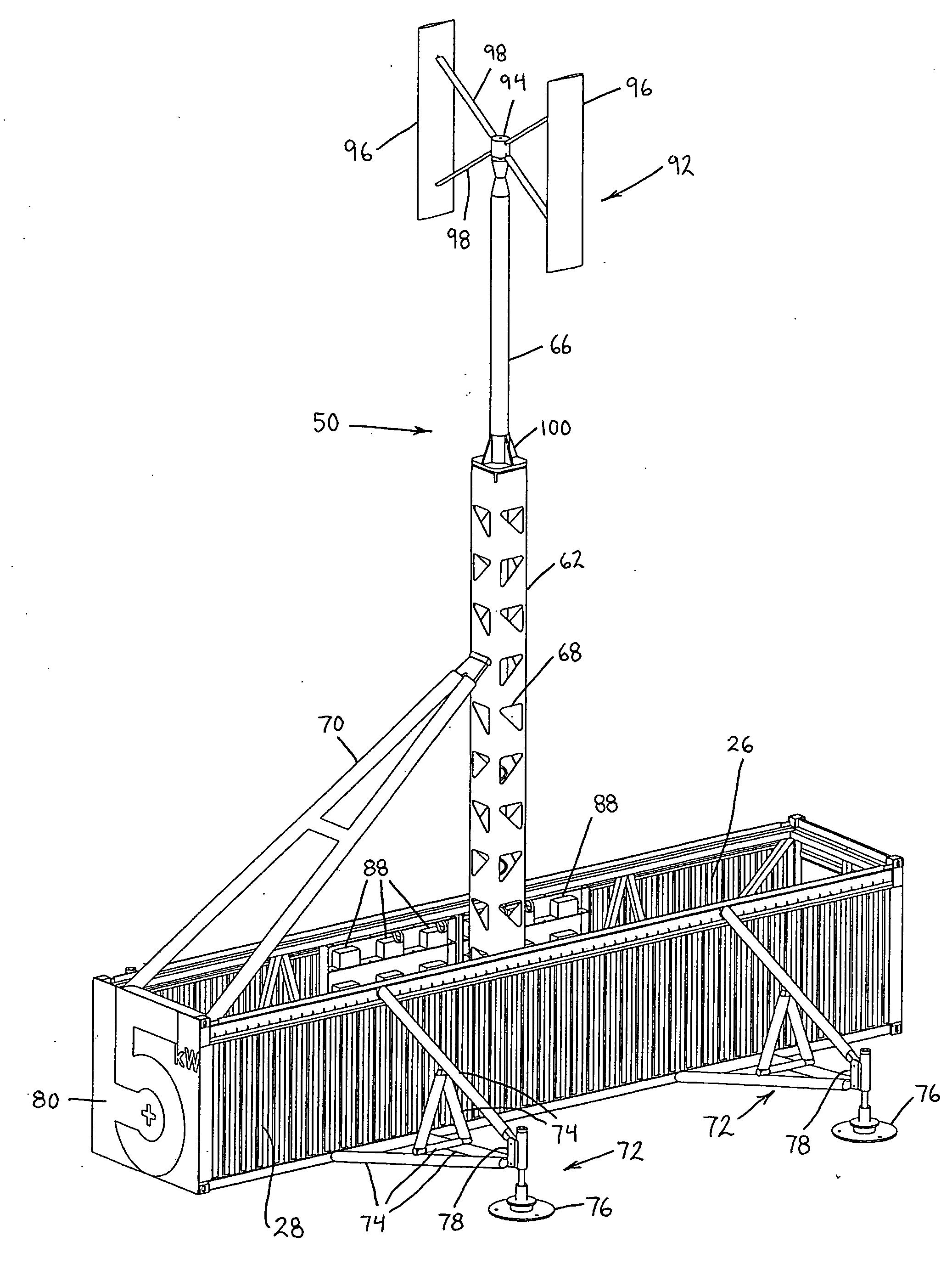
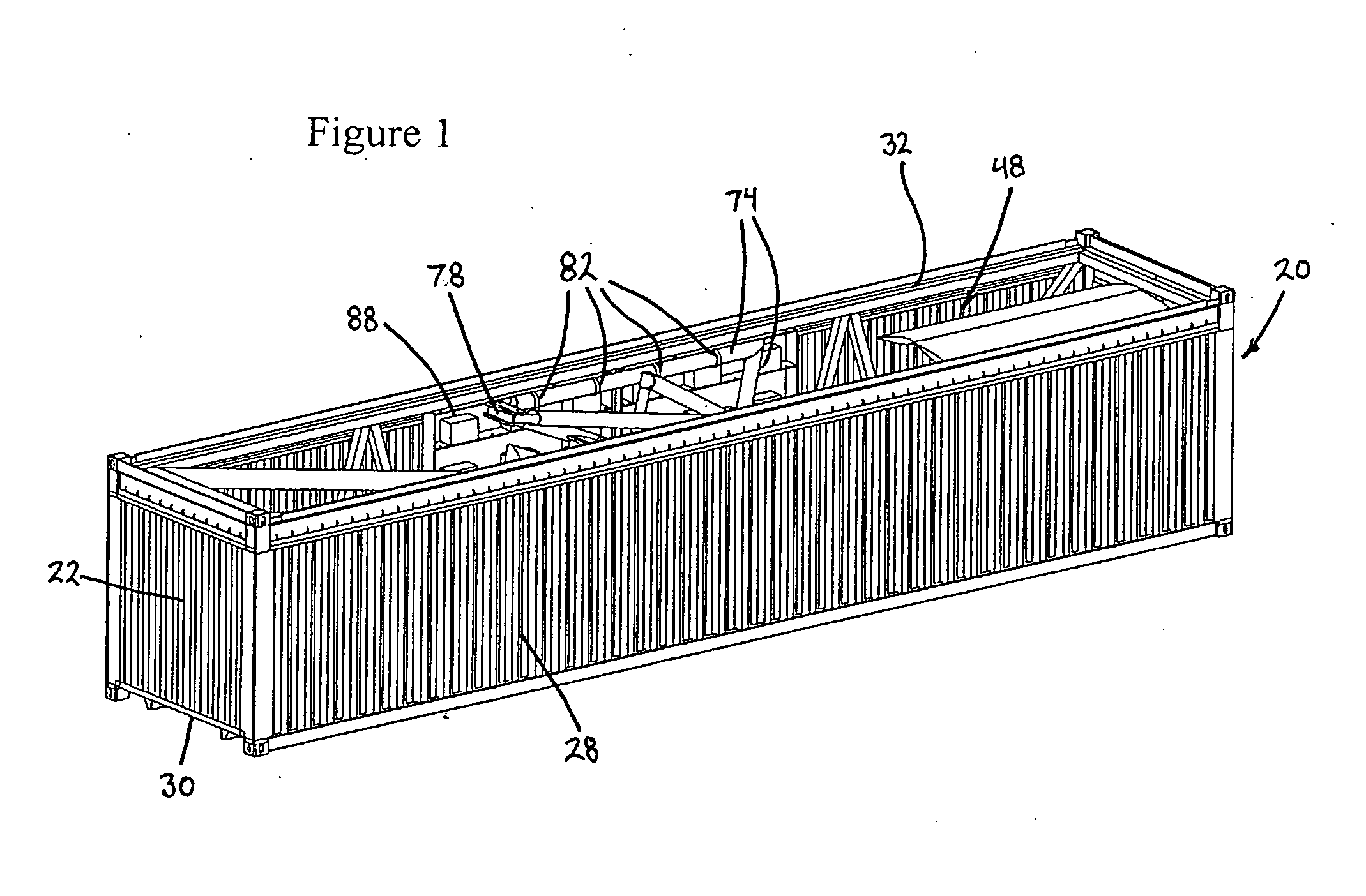
[0022]The isometric view provided by FIG. 1 shows a collection 48 of elements received, in a packed condition, within a standard, readily available 40′ ISO (International Organization for Standardization) shipping container 20. The packaged collection 48 of elements is utilized in a manner to be described to place a vertical axis turbine 50 (FIG. 3) into operational condition. The container 20 is entirely conventional, and, as illustrated in FIGS. 1 and 6, includes a pair of end walls 22, 24, a pair of side walls 26, 28, a floor 30, and an open top 32.

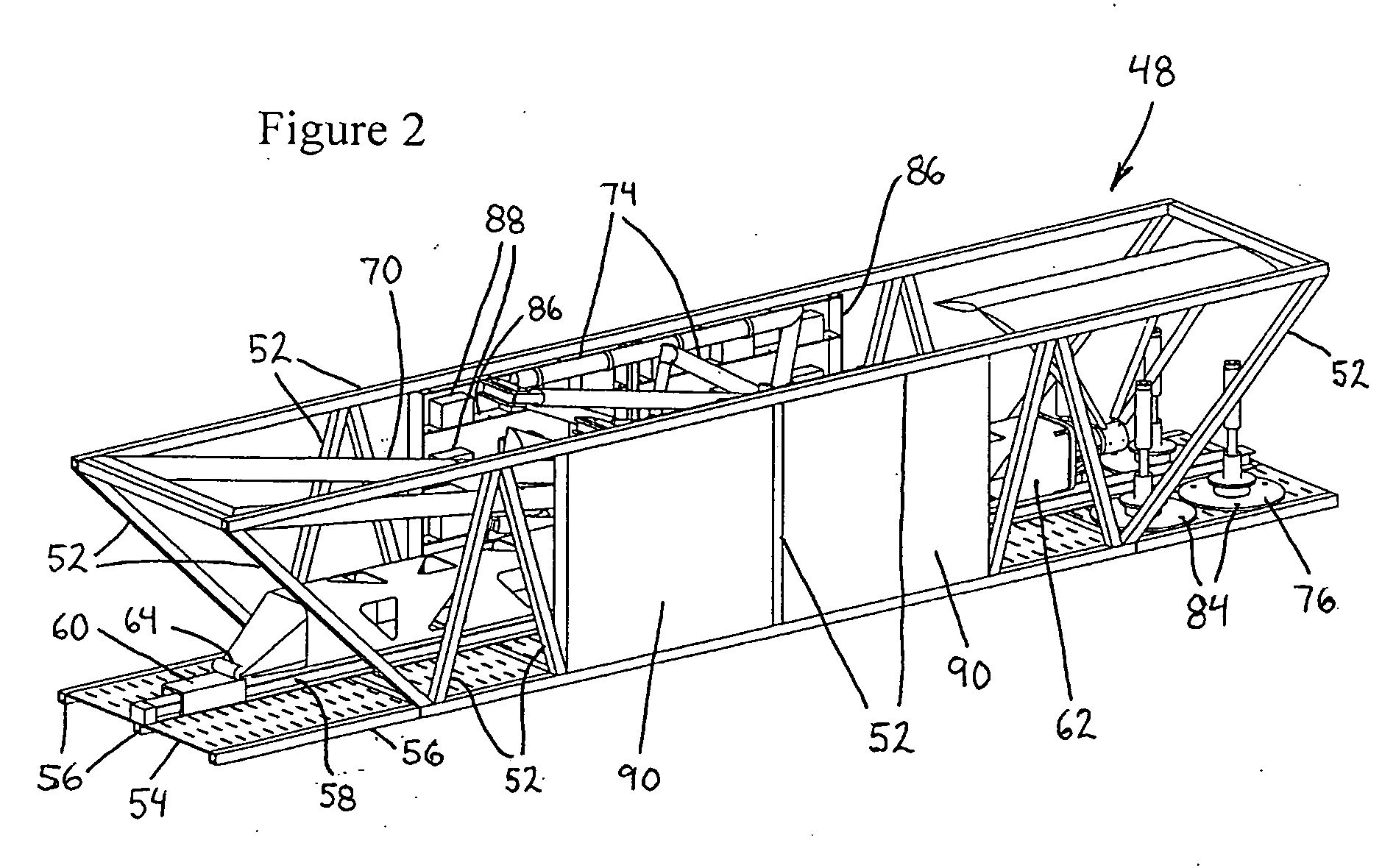
[0023]FIG. 2 illustrates the collection 48 of elements without the shipping container 20. This collection 48 has numerous individual components, including a steel reinforcing frame 52, a perforated sheet steel floor 54, floor reinforcing and support rails 56, producing a raised floor level within the container 20 providing space for cabling and other services, a tractor element guide member, such as a guide rail 58, secured to the floo...


PUM


Abstract

A portable, selectively deployable power supply and storage arrangement includes a frame, a floor securable to the frame and having a longitudinally extending guide member provided thereon, a mast assembly having a first end pivotally connected to a tractor element slidable along the guide member and a second end opposite the first end, and a wind turbine receivable at the second end of the mast assembly. A support is pivotally connected to and extends between both the frame and a portion of the mast assembly so that, upon displacement of the tractor element along the guide member, the support produces movement of the mast assembly between retracted and deployed positions. To facilitate transportation and relocation of the power supply and storage arrangement, the frame, the floor, the mast assembly, the wind turbine, and the support are configured to define a single unit and are collectively receivable in a shipping container.

Description

[0001]This application claims priority under 35 U.S.C. §119(e) to U.S. provisional application Ser. No. 61 / 362,216, filed Jul. 7, 2010, the entire disclosure of which is incorporated by this reference into the present application.BACKGROUND OF THE INVENTION[0002]1. Field of the Invention[0003]The present invention generally relates to deployable wind turbine systems incorporating used and discarded shipping containers or similar elements.[0004]2. Description of Related Art[0005]Wind turbines are used for energy generation worldwide, and consist of a rotary engine in which the kinetic energy of a moving fluid is converted into mechanical energy by causing a bladed rotor to rotate. Some bladed rotors are oriented along a vertical axis (Vertical Axis Wind Turbines (VAWT)), and some are oriented along a horizontal axis (Horizontal Axis Wind Turbines (HAWT)). Some turbines are installed for use on a fixed site, and some are portable.[0006]The ATOPIA RESEARCH Inc. document titled PITCH_AF...

Claims


Application Information

Patent Timeline
Patent Type & Authority Applications(United States)
IPC IPC(8): F03D9/00
CPCE03B3/03Y10S415/907E04H3/10E04H12/182E04H12/187Y02A20/108Y10T137/794Y10T137/0318Y02A20/00
Inventor HARRISON, JANETURNBULL, DAVIDKING, DOUG
Owner ATOPIA RES
Why Eureka
Try Eureka