Apparatus for drying scuba diving gear

a technology for diving gear and accessories, which is applied in the direction of machine supports, other domestic objects, and underwater equipment, can solve the problems of affecting the air circulation of the equipment, and the overhead support is simply inadequate to handle the combined weight, so as to facilitate the air circulation, and facilitate the effect of erecting

Inactive Publication Date: 2006-04-11
BAIN MICHAEL J +1
View PDF8 Cites 20 Cited by
  • Summary
  • Abstract
  • Description
  • Claims
  • Application Information

AI Technical Summary

Benefits of technology

[0008]Another object of this invention is to provide an exceptional apparatus for drying scuba diving gear that can be easily erected to stand on the ground whereby the apparatus can be used in locations where there are no overhead supports from which to hang the diving gear.
[0009]Another object of this invention is to provide an excellent apparatus for drying scuba diving gear that maintains sufficient separation between each piece of diving gear hanging from the apparatus so as to facilitate improved air circulation around and between the equipment for decreasing the time required to dry the gear.
[0010]Another object of the invention is to provide a desirable apparatus for drying scuba diving gear that can be easily disassembled for compact storage and yet is simple to construct, not complicated to maintain, and highly reliable to use.SUMMARY OF THE INVENTION

Problems solved by technology

The broad shoulders of the hangers decrease the likelihood of the type of crease being created that can weaken and damage the material, thereby leading to tears or holes to this equipment.
There are many occasions where the diver needs to dry his gear on the beach or in his hotel room and there is either no overhead support or one simply inadequate to handle the combined weight of the wet pieces of equipment hanging from it.

Method used


Image

  • Apparatus for drying scuba diving gear
  • Apparatus for drying scuba diving gear
  • Apparatus for drying scuba diving gear

Examples


Embodiment Construction

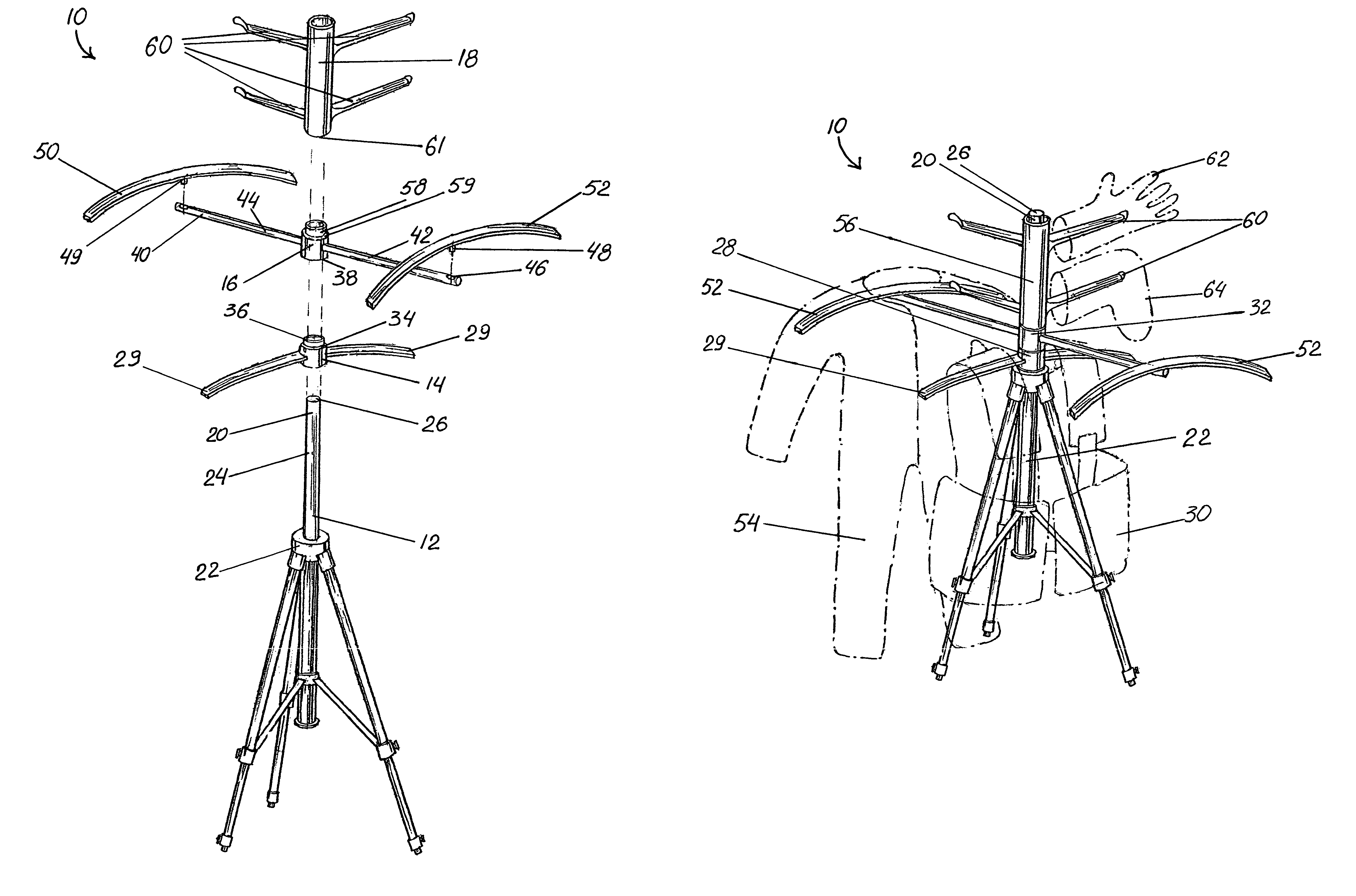
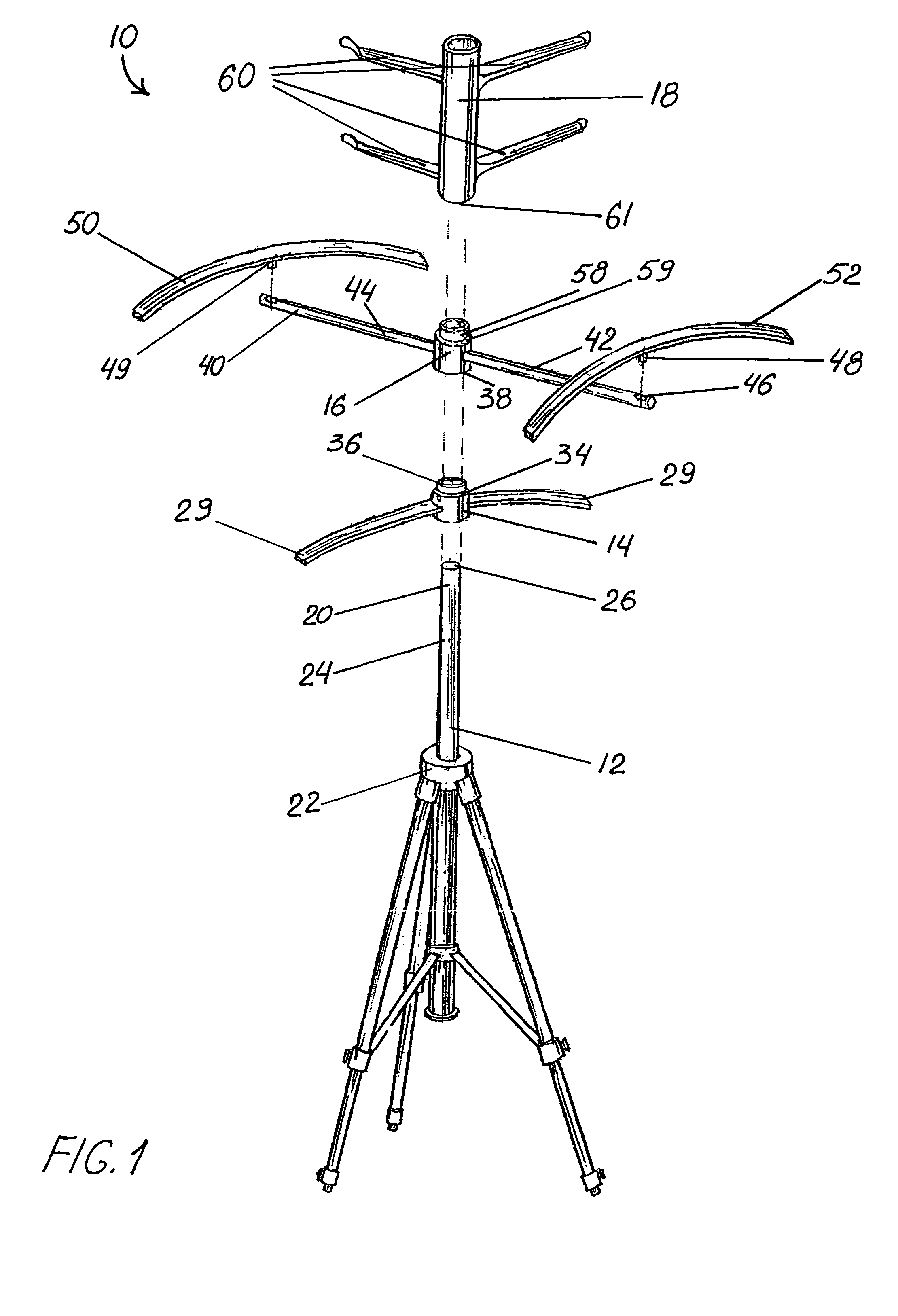
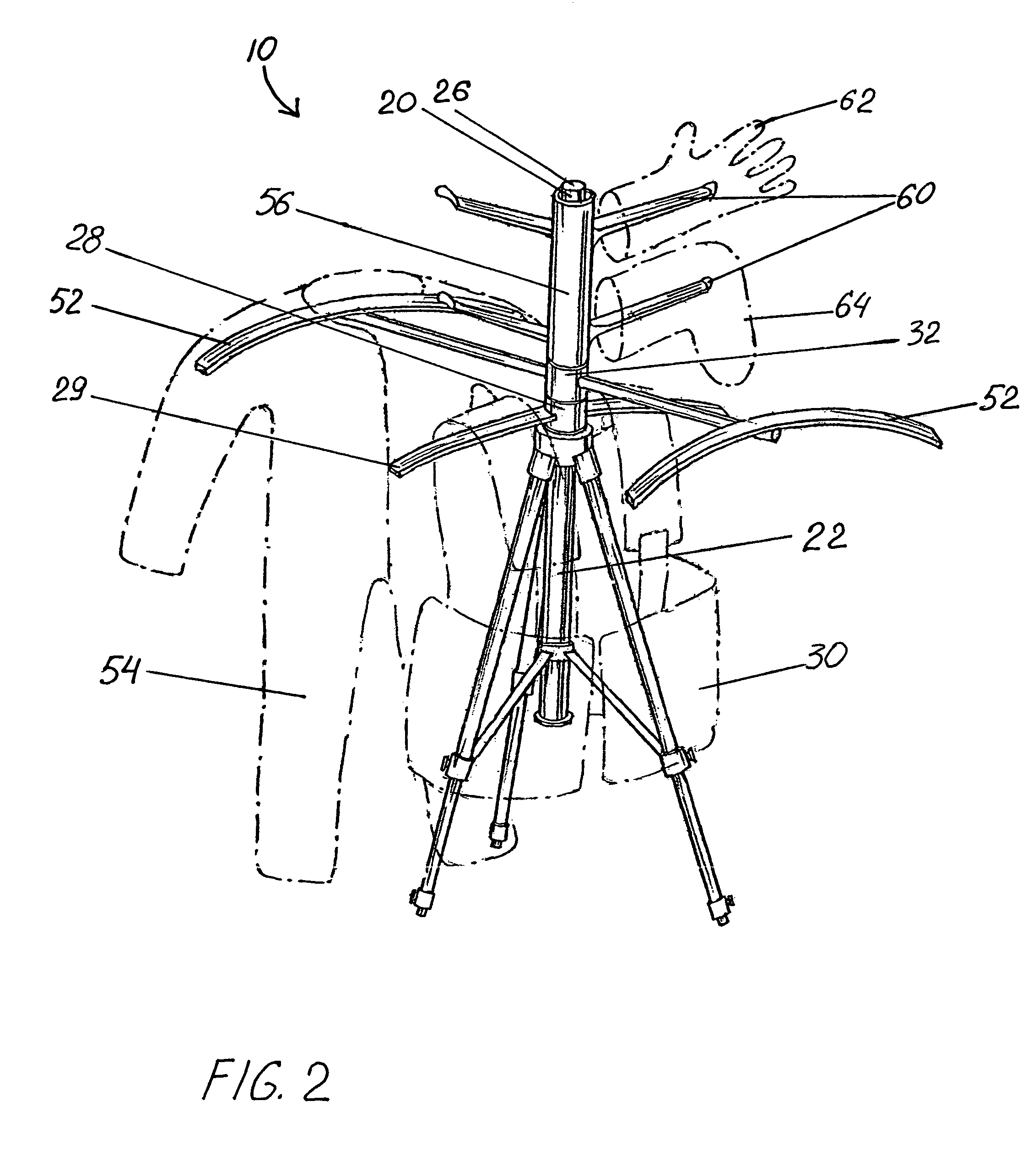
[0024]The drawings illustrate an improved apparatus 10 for drying scuba diving gear in accordance with this invention. Apparatus 10 is comprised of support member 12 and first, second and third hanger sub-assemblies 14, 16, 18. The support member 12 in the preferred embodiment shown in FIGS. 1–2 is shaft 20. Shaft 20 is a rigid structure, vertically mounted to tripod 22 in a manner that allows shaft 20 to telescopically extend or retract axially whenever tripod 22 is respectively erected for use or collapsed for storage.

[0025]As seen in FIGS. 1–2, when extended outward, shaft 20 has upper portion 24 and top end 26. First hanger sub-assembly 14 includes tubular first sub-assembly hub 28. Hub 28 is sized to be slidably received by shaft 20 when placed over top end 26. Hub 28 is further sized to rotate at its point of engagement with shaft 20.

[0026]Two hanger extensions 29 are rigidly attached to the outer surface of first sub-assembly hub 28, one opposite from the other, in a substant...


PUM


Abstract

An apparatus for drying scuba diving gear is provided having a support member and first, second and third hanger sub-assemblies removably, slidably engageable with respect to the support member. The sub-assemblies are in vertical alignment with one another at their point of engagement with the support member. Each sub-assembly is adapted for specific pieces of scuba gear. Preferably, the support member is a vertically disposed shaft telescopically secured to an erectable / collapsible tripod assembly. An apparatus is also disclosed where the support member is a chain assembly having an attachment hook for attachment with respect to an overhead support at one end and a support bar to hold the hanger sub-assemblies upright in engagement with the chain assembly at the other end.

Description

FIELD OF THE INVENTION[0001]This invention is related generally to apparatus for drying wet garments and, more particularly, to apparatus for drying wet scuba diving gear.BACKGROUND OF THE INVENTION[0002]Interest in the sports of scuba diving and snorkeling continues to grow. Participation in these aquatic activities requires the enthusiast to utilize a wide range of equipment, often referred to as “gear”. This equipment includes a wet suit, hot skin, buoyancy compensator as well as other accessories such as diving gloves and boots.[0003]Since these garments can be quite expensive, most divers purchasing it are highly motivated to see that their gear receives proper care at all times. In particular, proper care includes seeing that each piece is treated in the correct manner when left to dry after a dive. Drying scuba gear is preferably done by placing the pieces on individual hangers where the hangers have broad shoulder-like supports. The hangers are then suspended off the ground ...

Claims


Application Information

Patent Timeline
Patent Type & Authority Patents(United States)
IPC IPC(8): A47F7/22A47G25/06A47G25/14A47G25/16A62B9/04B63C11/02
CPCA47G25/0664A47G25/16B63C11/02B63C2011/023A47G2025/1485
Inventor BAIN, MICHAEL J.BAIN, LISA M.
Owner BAIN MICHAEL J
Why Eureka
Try Eureka