Housing for the nacelle of a wind turbine

a wind turbine and nacelle technology, applied in the direction of machines/engines, liquid fuel engines, final product manufacturing, etc., can solve the problems of large geometric tolerance, large size of components, and associated large impurity, and achieve the effect of low production cos

Inactive Publication Date: 2011-03-31
KENERSYS GMBH
View PDF3 Cites 19 Cited by
  • Summary
  • Abstract
  • Description
  • Claims
  • Application Information

AI Technical Summary

Benefits of technology

[0011]In this respect it is the object of the invention to disclose a housing for the nacelle of a wind turbine which can be produced from parts that are economical to produce and at little production costs and can be erected easily.

Problems solved by technology

However, the size of the components, and the associated great imprecision with regard to geometric tolerances, which are systematic in FRP construction, are both problematic.
Also, relatively large-volume support structures must be constructed in the laminate for the function of the self-supporting structures, and given the tight space for the nacelles, this often leads to structural restrictions.
Moreover, shipping such large-sized elements is expensive, since as a rule the coverings comprise only a few large elements (often only one component).
The special shipments thus necessary are logistically complicated and entail high costs.
Metal (including aluminum) plates, however, as two-dimensional material, are not especially well suited from an economic standpoint, because of the relatively high density and costs (especially for aluminum).
That is, in these steel structures, non-self-supporting two-dimensional elements of FRP or a metal material are secured directly, using a large number of rivets or screws.
The result in these known systems is a large number of separation points, which are complicated in terms of production, since they have to be made tight against the effects of weather.
Experience shows that the costs for the system rise markedly if systematic sealing between the segments is to be attained, since in that case high degrees of precision and high expense for assembly are required.
Moreover, shipping the non-self-supporting two-dimensional elements is expensive; they have to be shipped in complicated, space-hogging holder structures.
The example disclosed involves a self-supporting construction of fiber reinforced plastic which is complicated in its construction.
Moreover, the individual components of the construction shown here, such as a side wall covering, are quite large, which leads to problems in adhering to tolerances, on the one hand, and in shipping these parts, on the other.

Method used


Image

  • Housing for the nacelle of a wind turbine
  • Housing for the nacelle of a wind turbine
  • Housing for the nacelle of a wind turbine

Examples


Embodiment Construction

[0045]In the drawings, in schematic basic views that are not to scale, individual views are shown of one exemplary embodiment for a housing of the invention for the nacelle of a wind turbine. These drawings and the description below of the exemplary embodiment shown in them are intended to promote understanding of the invention in its general scope and are not limiting.

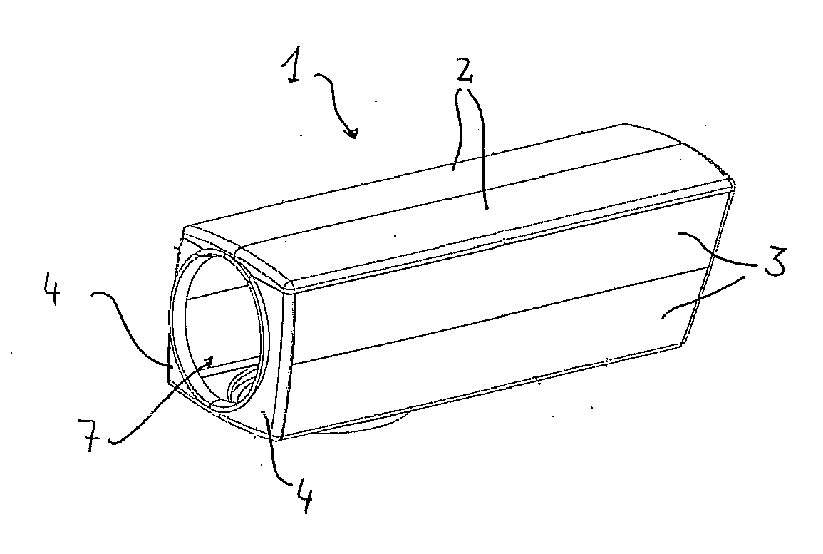
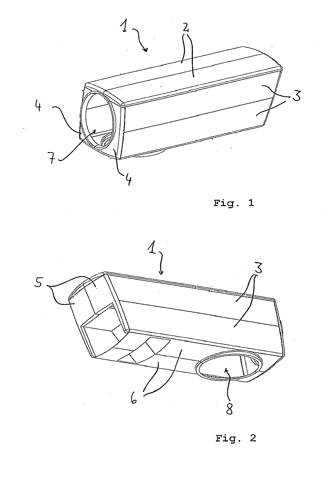
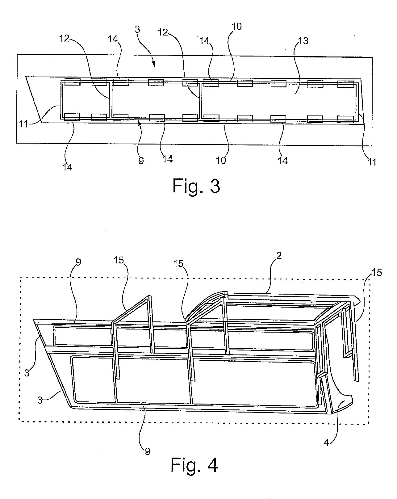
[0046]In FIGS. 1 and 2, the basic construction of a housing 1, constructed according to the invention from one support structure and a plurality of covering segments, for the nacelle of a wind turbine is shown in two different views. The housing 1 may also be called a machine house covering. On a support frame, not shown in detail in these drawings, a total of twelve covering segments are disposed and affixed; they are embodied as self-supporting and together form the housing 1. These segments are divided up into two ceiling segments 2, which as elongated components extend over the entire length of the housing 1 and a...


PUM


Abstract

Disclosed is a housing for the nacelle of a wind turbine, comprising a support structure (15) composed of tubes and braces, preferably made of metal, especially steel, or plastic, especially fiberglass reinforced plastic (FRP), and covering segments (2, 3, 4) which are fastened to said support structure (15). The housing is characterized in that the covering elements (2, 3, 4) have a coating surface made of plastic, especially FRP, and are self-supporting. Such a housing for the nacelle of a wind turbine can be manufactured with little effort from inexpensively produced parts and is easy to assemble. In particular, said housing combines the advantages of previously known structures that are self-supporting as a whole and the paneling of a support structure comprising parts that are not self-supporting without having the disadvantages thereof.

Description

FIELD OF THE INVENTION[0001]The invention relates to a housing for the nacelle of a wind turbine, having the characteristics of the preamble to claim 1.PRIOR ART[0002]Wind turbines have a tower on which a so-called nacelle, also called a machine house, is rotatably disposed. The rotor is disposed on the face end of this nacelle and is connected to a rotor shaft that protrudes into the nacelle. In the nacelle itself, optionally, there is a gear, as well as the generator used to generate current and possibly further components.[0003]On the one hand for protection against the effects of weather but on the other also to deflect wind loads, the nacelle has to be provided with, or closed with, a covering or a housing.[0004]For that purpose, various approaches and procedures are known from the prior art.[0005]For instance, self-supporting constructions of plastic, typically FRP, are known, which comprise a few segments, such as two lower parts and a cap. However, the size of the components...

Claims


Application Information

Patent Timeline
Patent Type & Authority Applications(United States)
IPC IPC(8): F04D29/44
CPCF03D1/001F03D11/00F05B2240/14Y02E10/728Y02E10/722Y02E10/726Y02E10/721F03D13/10F03D80/00Y02E10/72Y02P70/50F03D80/60
Inventor ELSENHEIMER, MARTINABECKER, MARKUS
Owner KENERSYS GMBH
Why Eureka
Try Eureka