Driver's airbag module assembly structure

a technology for airbag modules and assembly structures, which is applied in the directions of pedestrian/occupant safety arrangements, vehicular safety arrangments, vehicle components, etc., can solve the problems of increasing manufacturing costs and weight, increasing production costs, and lowering productivity, so as to simplify the assembly process, improve the assembly structure of mounting plates and cover members, and reduce manufacturing costs

Inactive Publication Date: 2007-06-14
AUTOLIV DEV AB
View PDF12 Cites 14 Cited by
  • Summary
  • Abstract
  • Description
  • Claims
  • Application Information

AI Technical Summary

Benefits of technology

[0030] An object of the present invention is to provide a driver's airbag module having an improved assembly structure of a mounting plate and a cover member, simplifying an assembly process, and reducing manufacturing cost.

Problems solved by technology

However, in the conventional art, since the mounting plate and the cover member are assembled by fastening the bolt, the assembly process is complicated and the number of parts is increased, thereby increasing manufacturing cost and weight.
However, since all of the conventional art described above requires strong external force for coupling the cover member and the mounting plate, assembly is a time consuming operation, therefore lowering productivity.
In addition, since the base plate should be strongly pressed and assembled into the insert, its assembly operation is also difficult.

Method used


Image

  • Driver's airbag module assembly structure
  • Driver's airbag module assembly structure
  • Driver's airbag module assembly structure

Examples


Embodiment Construction

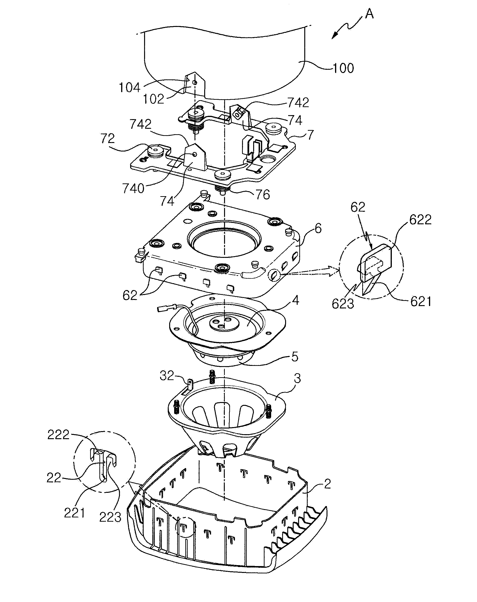
[0059] Hereinafter, a first exemplary embodiment of the present invention will be described with reference to FIGS. 2 and 3.

[0060] As shown in FIGS. 2 and 3, a driver's airbag module A in accordance with the present invention includes an inflator 4 for generating gas by igniting an exploder, an airbag 5 expanded and deployed toward a driver by the gas generated by the inflator 4, a cage 3 covering the inflator 4, a mounting plate 6 for accommodating the inflator 4, the airbag 5, and the cage 3, and fixed in a cover member 2 provided at a handle, and a horn plate 7 installed on the mounting plate 6 and coupled with a steering wheel 100.

[0061] The horn plate 7 and the mounting plate 6 are fixed to each other by a mounting bolt 72 in a spaced-apart state, and a horn spring 76 is interposed at an outer periphery of the mounting bolt 72 to resiliently support the horn plate 7.

[0062] In addition, a plurality of fixing clips 62 are formed at an outer surface of the mounting plate 6, and...


PUM


Abstract

Provided is a driver's airbag module assembly structure including: an inflator for generating gas by igniting an exploder; an airbag inflated toward a driver by the gas generated by the inflator; a cage covering the inflator; a mounting plate for accommodating the inflator, the airbag, and the cage to be fixed in a cover member disposed at a handle; and a horn plate installed between the mounting plate and a steering wheel, characterized in that the mounting plate has a plurality of fixing clips formed at its outer surface, the cover member has a plurality of coupling holes coupled with the fixing clips, the horn plate is provided with a bracket having an angled tip and a fastening hole, and the steering wheel is provided with a groove having an angled step corresponding to the bracket of the horn plate. Therefore, hooks of a mounting plate push flexible pieces formed at coupling holes of a cover to allow the mounting plate and the cover to be easily coupled with each other. In addition, since the hooks are closely inserted into lower horizontal holes, movement of the hooks can be reduced. Further, the hooks do not separate from the coupling holes when the airbag is deployed.

Description

CROSS-REFERENCE TO RELATED APPLICATIONS [0001] Republic of Korea Application No. 10-2005-0099362, filed Oct. 20, 2005; Republic of Korea Application No. 10-2006-0007456, filed Jan. 24, 2006; and Republic of Korea Application No. 10-2006-0068570, filed Jul. 21, 2006. BACKGROUND OF THE INVENTION [0002] 1. Field of the Invention [0003] The present invention relates to a driver's airbag module assembly structure, and more particularly, to a driver's airbag module assembly structure enabling easy assembly of an airbag module installed in a steering wheel. [0004] 2. Description of the Prior Art [0005] Generally, an airbag system for an automobile is a safety device for reducing injury due to impact in a collision by instantly inflating an airbag installed in a steering wheel or a glove box between a driver and the steering wheel or between a passenger and the glove box. The airbag system works independently from a seat belt. [0006] The airbag system for driver / passenger has an inflator fo...

Claims


Application Information

Patent Timeline
Patent Type & Authority Applications(United States)
IPC IPC(8): B60R21/203B60R21/217B60R21/20
CPCB60R21/2035B60R21/217
Inventor KIM, TAE-HOONJEONG, SE-HWA
Owner AUTOLIV DEV AB
Why Eureka
Try Eureka