Id tag

a technology of id tags and tags, applied in the field of id tags, can solve the problems of id tags being disfunctional, unable to protect personal information, and unable to be reused,

Inactive Publication Date: 2007-06-14
NEC CORP
View PDF4 Cites 8 Cited by
  • Summary
  • Abstract
  • Description
  • Claims
  • Application Information

AI Technical Summary

Benefits of technology

[0030] In the ID tag of the present invention, the time switch may include a first metal interconnection and a second metal interconnection provided in the circuit in parallel with each other, as being spaced by a predetermined distance; and a gap portion disposed between the first and second metal interconnections, and the time swich is configured as allowing the gap portion to turn into a conductive state so as to short-circuit the first and...

Problems solved by technology

The conventional ID tag with the nullification mechanism, however, needs artificial nullification, and negligence of this processing may fail in safely protect personal information.
Another problem is that the nullification took place as described in the above directly means that the ID tag is disfunctioned and made unrecyclable.
For an exemplary case where a consumer buys a product having the ID tag integrated therein, nullific...

Method used


Image

  • Id tag
  • Id tag
  • Id tag

Examples


first embodiment

[0061] First, a general configuration of an ID tag having a time switch according to the present invention will be explained.

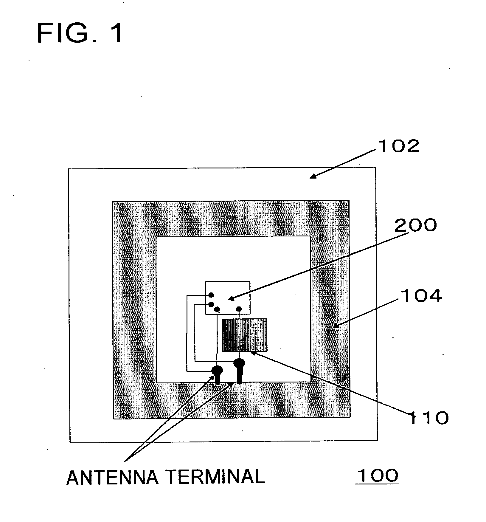
[0062]FIG. 1 is a drawing showing an internal structure of an exemplary RFID tag of this embodiment. The RFID tag 100 has a circuit including an antenna (coil antenna 104) and an IC chip 200, and a nullification unit (nullification mechanism 110) isolating the circuit. The nullification unit (nullification mechanism 110) includes a time switch isolating the circuit when a predetermined time limit for operation has reached after the start of use of the ID tag. A coil antenna 104, an IC chip 200 and a nullification mechanism 110 are provided on a substrate 102.

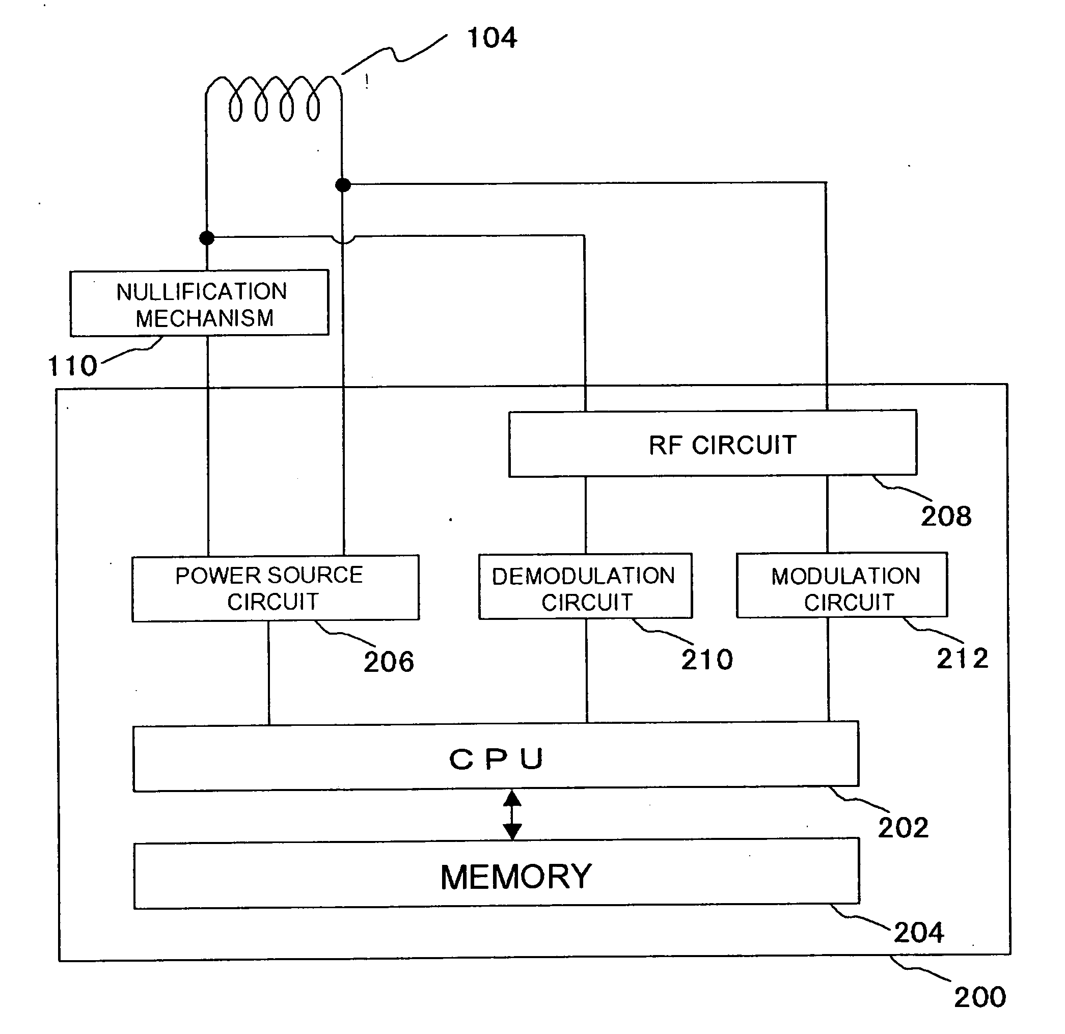
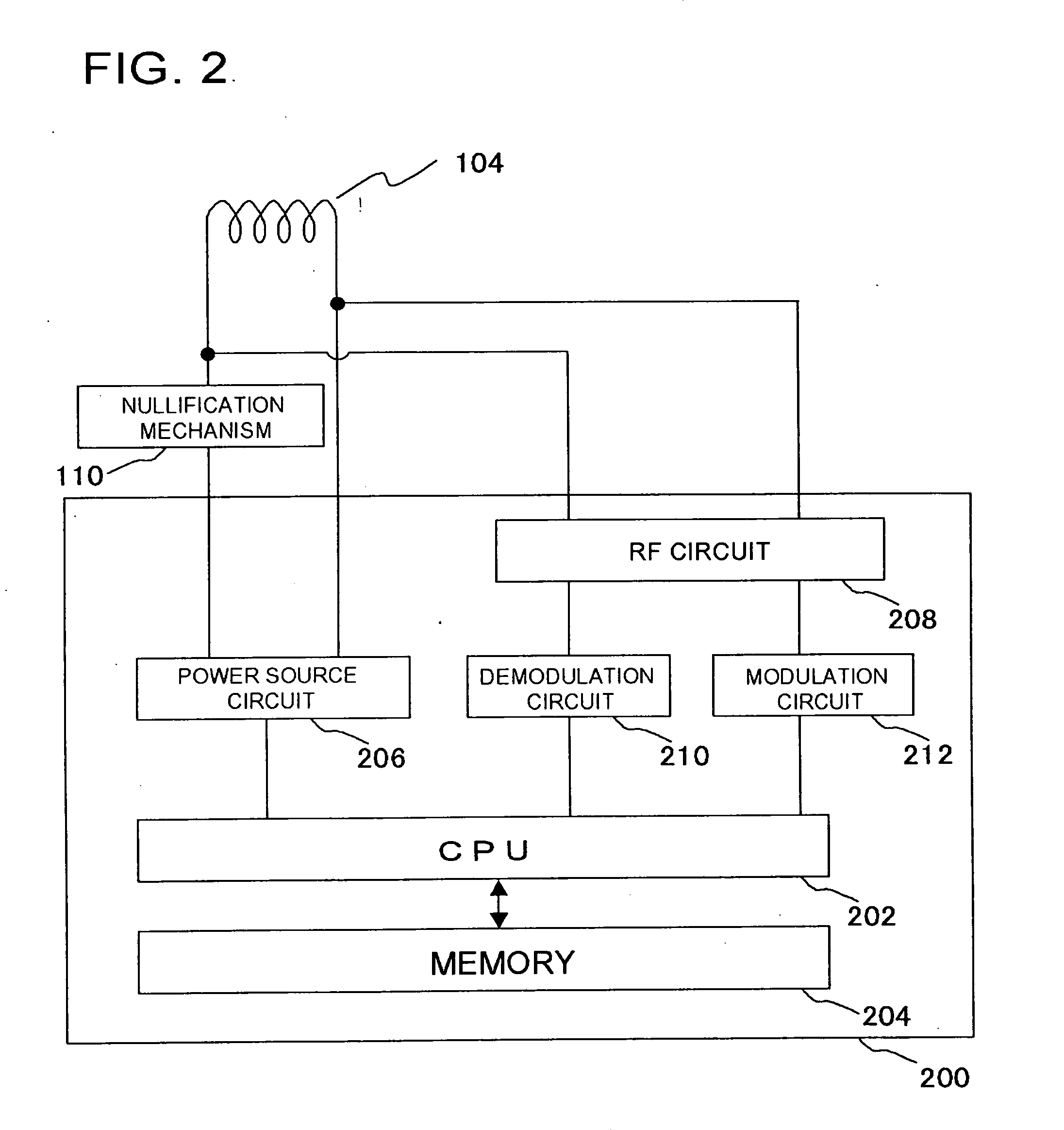
[0063] The IC chip 200 is a thin chip having a communication circuit which takes part in transmission of various data to or from an external reader / writer, and a memory storing various data incorporated therein. The coil antenna 104 applicable herein may be such as being formed by pattern-forming printin...

second embodiment

[0072] In this embodiment, an exemplary time switch included in the nullification mechanism 110 will be explained.

[0073] (General Structure)

[0074]FIG. 4 is a drawing showing a general configuration of a solid electrolyte switch 300 as an example of the time switch according to the present invention. The switch makes use of a phenomenon such that a conduction channel formed in the solid electrolyte film in the initial state thereof disappears with time.

[0075]FIG. 4(a) is a drawing schematically showing a state of the solid electrolyte switch 300 in the switched-off state. As shown in the drawing, the solid electrolyte switch 300 has a pair of electrodes 302 opposed with each other, and a solid electrolyte 308 held therebetween. An ion supplying layer 304 is provided on the inner surface of one of the electrodes 302. Metal ions 306 released from the ion supplying layer 304 reside in the solid electrolyte 308 in a distributed manner. In an equilibrium state, there is no electro-cond...

third embodiment

[0112] This embodiment shows an example of a narrow metal line composed of a metal or a semiconductor, which can be converted into an insulating material through oxidation, applied to the time nullification switch. FIG. 10 is a schematic drawing of the RFID tag of this embodiment.

[0113] The RFID tag 100 has the circuit including the antenna (coil antenna 104) and the IC chip 200, and the nullification unit (time switch 112) isolating the circuit. The nullification unit (time switch 112) isolates the circuit when a predetermined time limit for operation has reached after the start of use of the ID tag. The coil antenna 104, the IC chip 200 and the nullification mechanism 110 are provided on the substrate 102.

[0114] The IC chip 200 is a thin chip having a communication circuit which takes part in transmission of various data to or from an external reader / writer, and a memory storing various data incorporated therein. The coil antenna 104 applicable herein may be such as being formed...


PUM


Abstract

When a predetermined voltage is applied between electrodes (302), metal ions deposit in a solid electrolyte (308), and thereby a conduction channel (310) is formed therein. The solid electrolyte switch (300) is thus turned on. Because this deposition mechanism is reversible, application of reverse voltage between the electrodes of the solid electrolyte switch (300) already turned on makes the deposited metal atoms to migrate in the solid electrolyte to thereby thin the conduction channel 300, thereby the channel finally disappears, and the solid electrolyte switch (300) is turned into a non-conductive state. Use of this switch successfully realizes an IC tag which can automatically be nullified without artificial nullification.

Description

TECHNICAL FIELD [0001] The present invention relates to an ID tag having a nullification unit. BACKGROUND ART [0002] Physical distribution using ID tags has been attracting public attention in recent years. The ID tag has a memory storing information on commodities, information on distribution history of commodities or the like, and is allowed to access the memory at any time when an external signal is received. A system using the ID tag enables an efficient management never available before. [0003] On the other hand, this sort of system, capable of linking the product information with private information, is apprehended to invade consumers' privacy. For example, when a consumer buys a product having an ID tag integrated therein, it is anticipated that information in the tag may be read by a malicious third party, and this raises a possibility of tracing to what purpose the product is used, or what kind of products the customer carries. [0004] As a preventive measures against such i...

Claims


Application Information

Patent Timeline
IPC IPC(8): G08B13/14H04Q5/22G08B1/00G06F21/60G06F21/62G06F21/79G06K19/073G06K19/077
CPCG06K19/0723G06K19/073G06K19/07345G06K19/07749G06K19/07779G06K19/07783G08B13/2417
Inventor HATTORI, WATARUHONGO, HIROONIHEI, FUMIYUKISUNAMURA, HIROSHI
Owner NEC CORP
Why Eureka
Try Eureka