
Driving method of self-luminous type display unit, display control device of self-luminous type display unit, current output type drive circuit of self-luminous type display unit

a display unit and display control technology, applied in static indicating devices, instruments, electroluminescent light sources, etc., can solve the problems of significant affecting costs, uneven luminance, and output current variability, and achieve the effect of suppressing the increase in the circuit scal

Inactive Publication Date: 2007-06-14
TOSHIBA MATSUSHITA DISPLAY TECH
View PDF10 Cites 83 Cited by
  • Summary
  • Abstract
  • Description
  • Claims
  • Application Information

AI Technical Summary

Benefits of technology

[0072] The current output type semiconductor circuit, a display driving device, a display apparatus, and a method of outputting a current according to the present invention can suppress the increase in circuit scale lower when the number of output bits for a current driver increases.

Problems solved by technology

Thus, disadvantageously, output current may vary depending on a variation in characteristics among transistors.
As a result, luminance may be uneven.
This may result in flickers because of the high response speed of the organic light emitting device.
This problem is characteristic of the combination of the current driver, for which the output current is in proportion to the gray level, and the current output type display element, for which the input current is in proportion to the luminance.
This significantly affects costs.

Method used


Image

  • Driving method of self-luminous type display unit, display control device of self-luminous type display unit, current output type drive circuit of self-luminous type display unit
  • Driving method of self-luminous type display unit, display control device of self-luminous type display unit, current output type drive circuit of self-luminous type display unit
  • Driving method of self-luminous type display unit, display control device of self-luminous type display unit, current output type drive circuit of self-luminous type display unit

Examples


Embodiment Construction

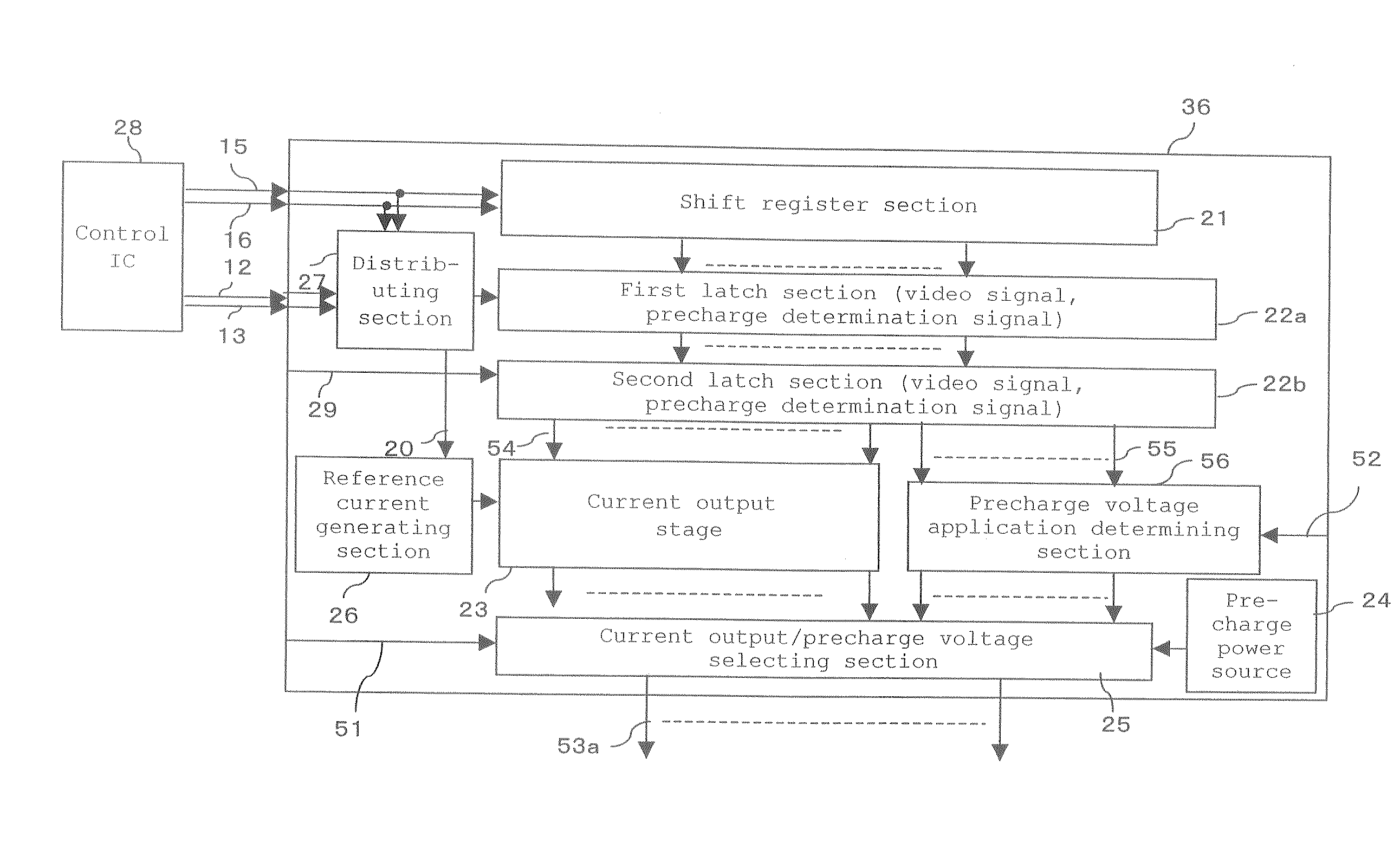
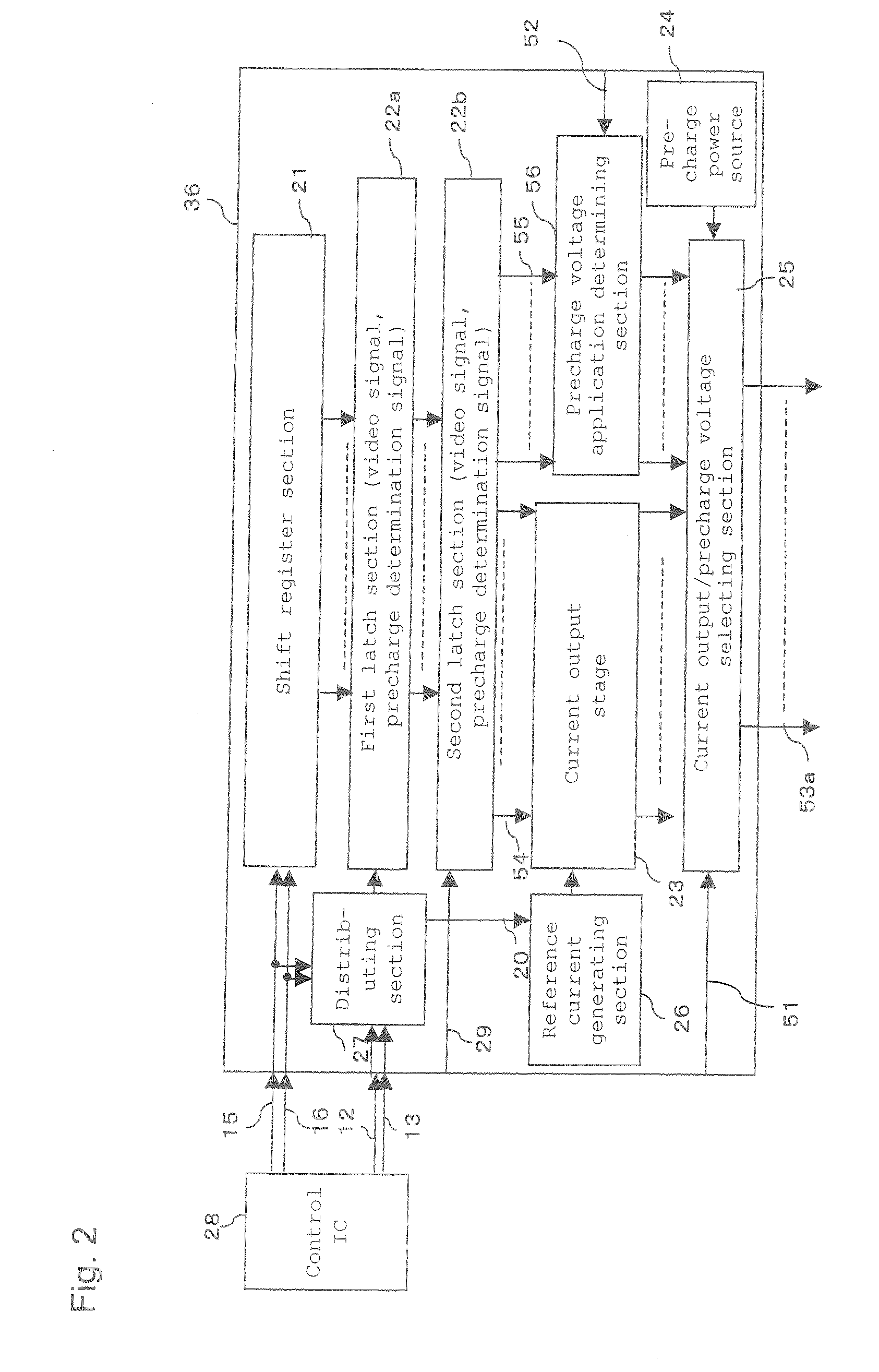
[0271] A current output type semiconductor circuit according to the present invention adds 2 bits to the lower side of conventional 6 bits. Thus, a current source is provided which outputs a quarter of a current value for a gray level display current source 103 conventionally used for 6-bit outputs. Then, three such current sources are added to allow 256-gray-level outputs. FIG. 24 shows a conceptual drawing of a current output stage that outputs 8 bits.

[0272] Since the use of 8-bit outputs increases the number of transistors by three, a configuration can be provided which requires only a small increase in circuit scale compared to an addition on the upper side.

[0273] An “I” value may be used to adjust a current value for white display (highest gray level display). The I value can be varied by controlling a reference current 89 in a configuration in FIG. 8. Accordingly, the adjustment can be accomplished by inputting control data 88 depending on an application.

[0274]FIG. 25 shows...


PUM


Abstract

The method includes applying a gray level current corresponding to a display gray level to each of pixel circuits for a first period, applying a display current based on the gray level current to the self-luminescent elements during a second period succeeding the first period to display corresponding the display gray level, and applying a precharge current to the self-luminescent device during a third period before the first period on the basis of a predetermined first condition.

Description

TECHNICAL FIELD [0001] The present invention relates to a method of driving a self-luminescent type display apparatus, a display control device for the self-luminescent type display apparatus, and a current output type driving circuit for the self-luminescent type display apparatus, which implement a method of driving a display apparatus using an organic light emitting device, for example, an organic field light emitting device, which is used in a driving semiconductor circuit or the like for current output which circuit is used for a display apparatus providing gray level display on the basis of a current quantity. BACKGROUND ART [0002] An organic light emitting device is a self-luminescent element and thus has the advantages of, for example, eliminating the need for a backlight required for a liquid crystal display apparatus and providing a large field of view. Accordingly, the organic light emitting device is expected as a next generation display apparatus. [0003]FIG. 4 is a sect...

Claims


Application Information

Patent Timeline
Patent Type & Authority Applications(United States)
IPC IPC(8): G09G3/30G09G3/32H05B44/00
CPCG09G3/2014G09G2360/16G09G3/3241G09G3/325G09G3/3283G09G2310/0248G09G2310/027G09G2310/0289G09G2310/0297G09G2320/0223G09G2320/0238G09G2320/0242G09G2320/0247G09G2320/0252G09G2320/0276G09G2320/041G09G2320/0693G09G2330/06G09G2330/08G09G2340/16G09G3/2074G09G2320/0257
Inventor TSUGE, HITOSHI
Owner TOSHIBA MATSUSHITA DISPLAY TECH
Learn More