Method, device, and computer program for determining range to a target

a computer program and range technology, applied in the direction of distance measurement, using reradiation, instruments, etc., can solve the problems of inhibiting the use of devices, conventional devices are unable to account for the parabolic trajectory of projectiles, and cannot account for the increase or decrease in distance to a targ

Active Publication Date: 2007-06-14
BUSHNELL +9
View PDF11 Cites 8 Cited by
  • Summary
  • Abstract
  • Description
  • Claims
  • Application Information

AI Technical Summary

Problems solved by technology

However, these conventional devices determine ranges which only represent a straight-line distance to a target and which fail to account for the parabolic trajectory of projectiles, such as a golf ball, intended for the target.
As a result, these conventional devices generate inaccurate results if a target is positioned above or below the device.
Conventional devices are unable to account for this increase or decrease in distance to a target caused by the trajectory of the projectile and the angle to the target.
As individuals often determine ranges to targets while outdoors on terrains of varying slopes, such as a golfer on a golf course, the inaccurate results generated by conventional range determining devices substantially inhibit the use of the devices and negate many beneficial aspects of the devices.
For instance, a golfer is unlikely to utilize a range finding device which provides inaccurate yardage measurements over sloping terrain and thus is forced to use multiple devices to determine a single accurate range or manually estimate or guess at the correct yardage based on the determined range.
Such use of estimations and multiple devices results in undesirable inconvenience and inaccuracy.

Method used


Image

  • Method, device, and computer program for determining range to a target
  • Method, device, and computer program for determining range to a target
  • Method, device, and computer program for determining range to a target

Examples


Embodiment Construction

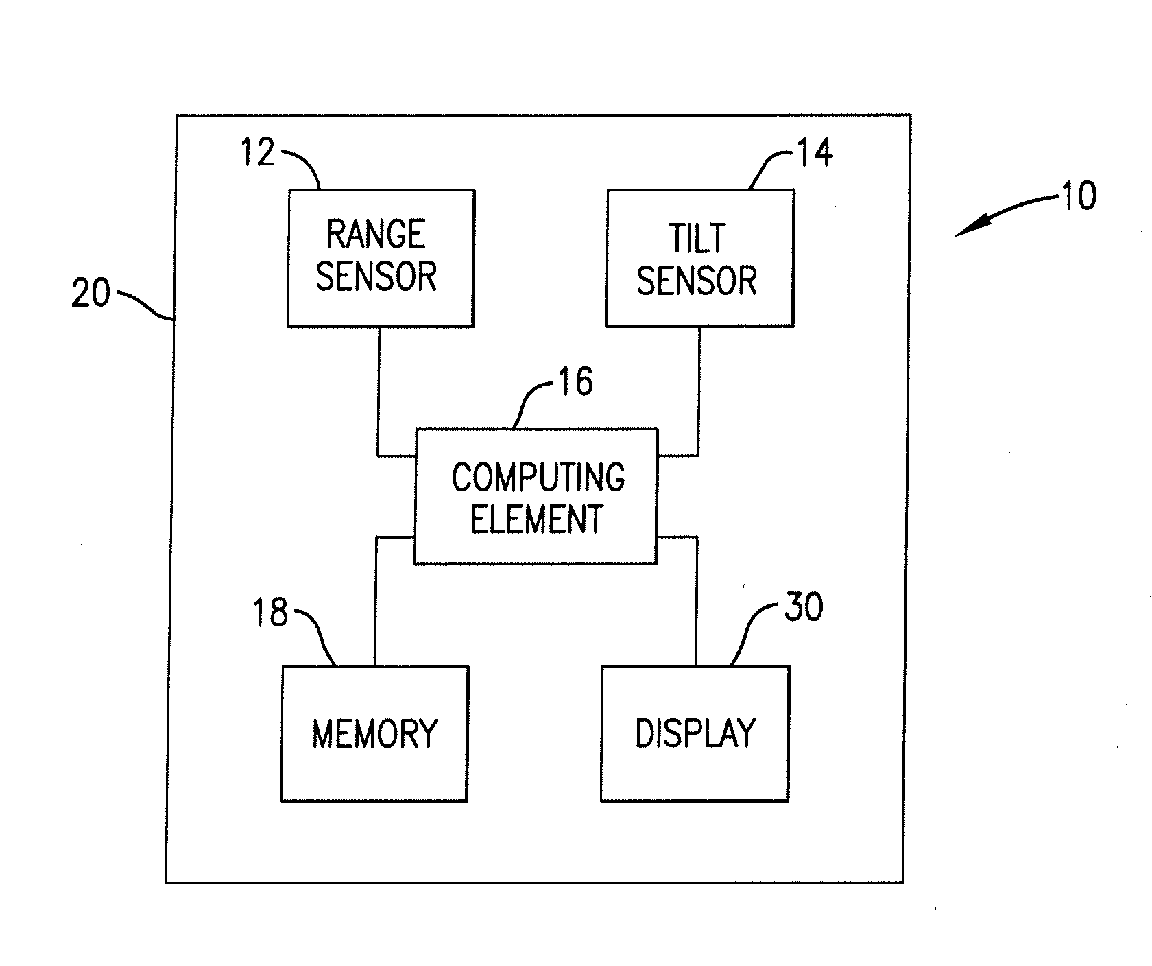
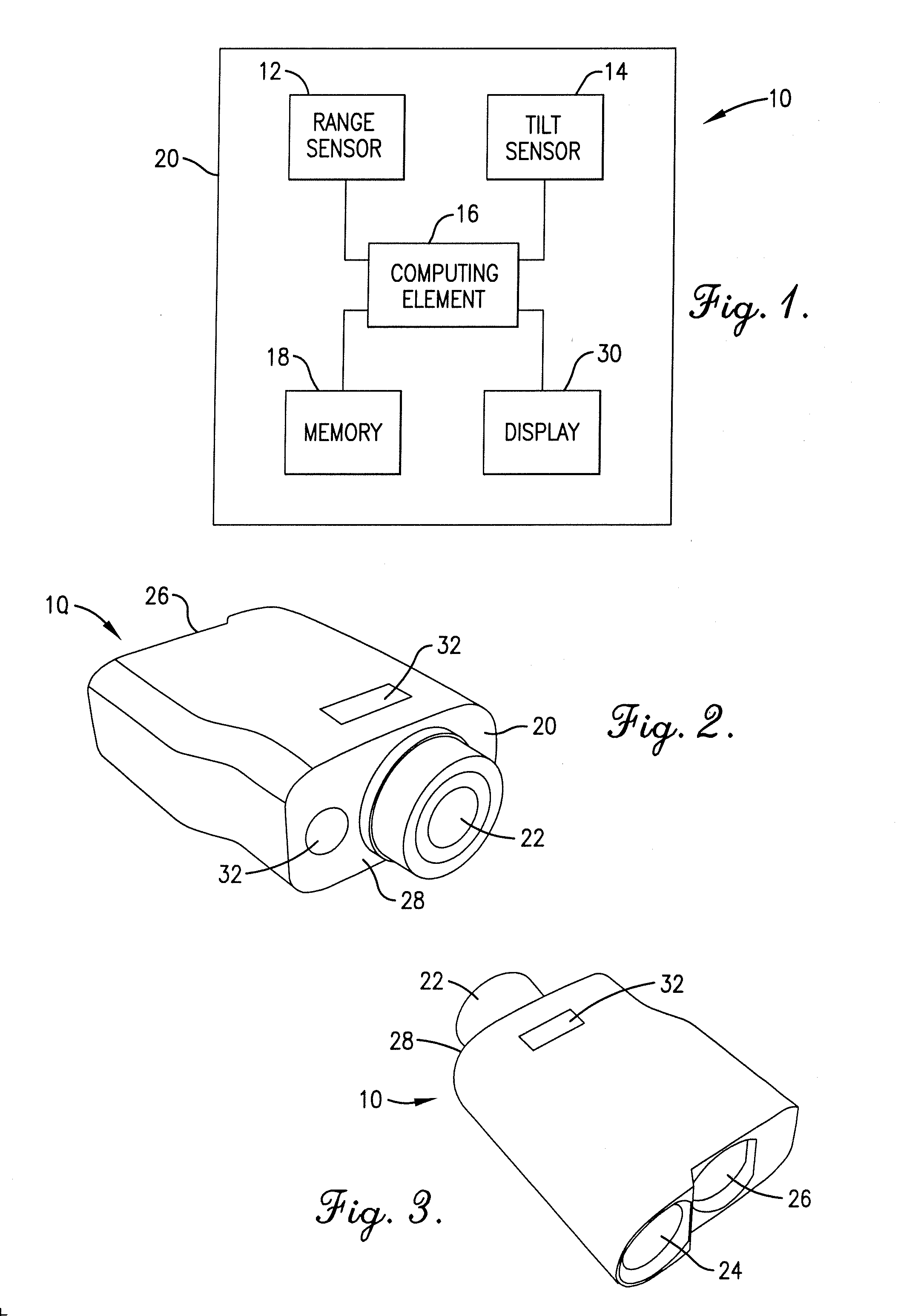
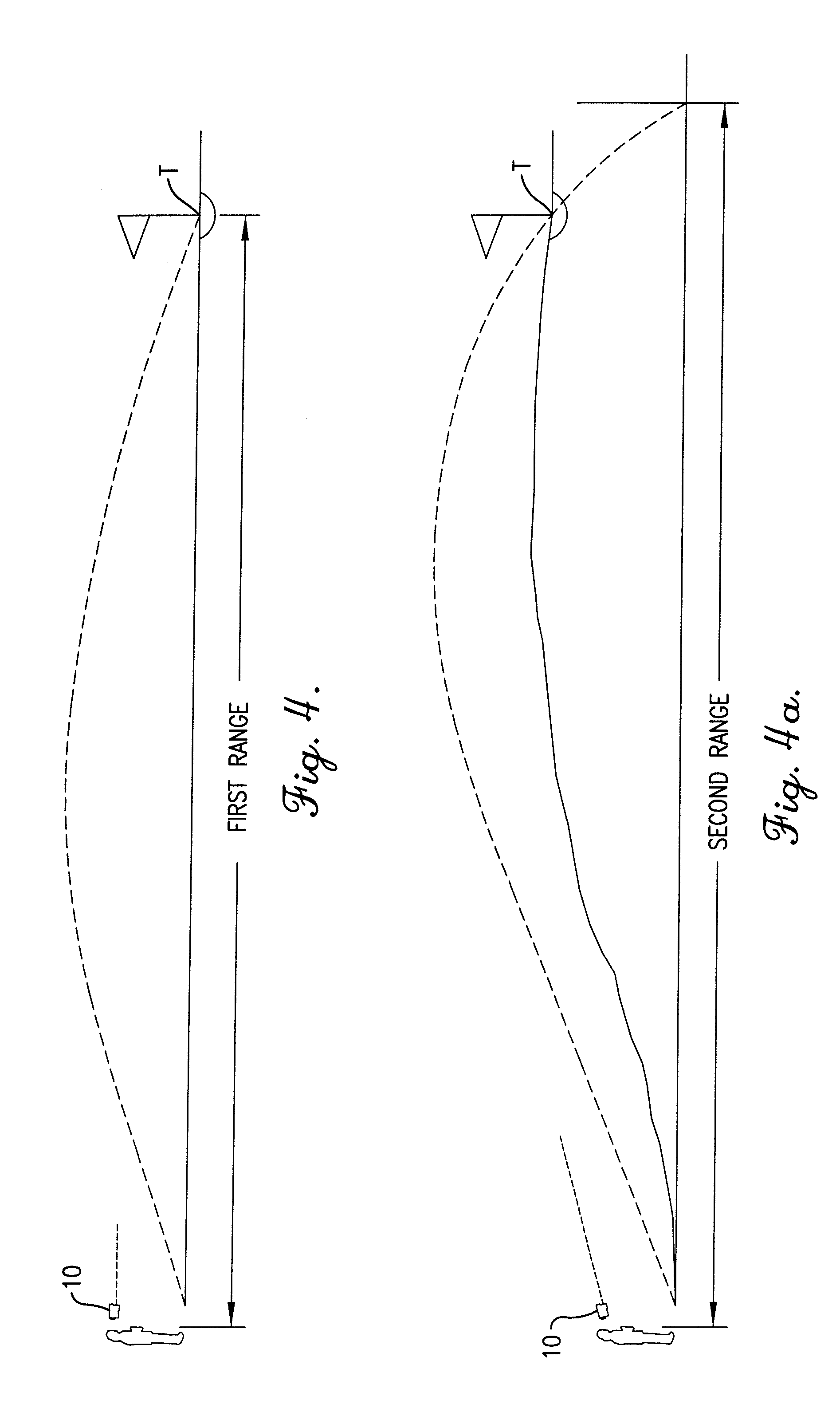
[0024] Turning now to the drawing figures, and particularly FIGS. 1-3, a device 10 is shown constructed in accordance with a preferred embodiment of the present invention. The device 10 broadly includes: a range sensor 12 for determining a first range to a target T; a tilt sensor 14 for determining an angle θ to the target T; a computing element 16 coupled with the range sensor 12 and tilt sensor 14 for determining a second range to the target T based on the first range and the determined angle θ; a memory 18 for storing data such as a computer program to control the functionality of the device 10; and a portable handheld housing 20 for housing the range sensor 12, the tilt sensor 14, the computing element 16, the memory 18, and other components described below.

[0025] The computer program controls input and operation of the device 10. The computer program includes at least one code segment stored in or on a computer-readable medium residing on or accessible by the device 10 for ins...


PUM


Abstract

A method, device, and computer program for determining range to a target is disclosed. Specifically, the invention provides a method, device and computer program for determining a second range to a target based on a first range to the target and an angle to the target such that the parabolic trajectory of a projectile is accounted for in determining the second range. The device generally includes a range sensor for determining a first range to a target, a tilt sensor for determining an angle to the target, and a computing element for determining a second range to the target based on the first range and the determined angle.

Description

RELATED APPLICATION [0001] The present application is a continuation patent application and claims priority benefit, with regard to all common subject matter, of earlier-filed U.S. patent application titled “METHOD, DEVICE, AND COMPUTER PROGRAM FOR DETERMINING A RANGE TO A TARGET”, Ser. No. 10 / 964,206, filed Oct. 13, 2004. The identified earlier-filed application is hereby incorporated by reference into the present application.BACKGROUND OF THE INVENTION [0002] 1. Field of the Invention [0003] The present invention relates to a method, device, and computer program for determining a range to a target. More particularly, the invention relates to a method, device, and computer program for determining a second range to a target based on a first range and an angle to the target such that the parabolic trajectory of a projectile is accounted for in determining the second range. [0004] 2. Description of the Related Art [0005] It is often desirable to determine accurate ranges to targets in...

Claims


Application Information

Patent Timeline
Patent Type & Authority Applications(United States)
IPC IPC(8): G01C3/08
CPCA63B2220/13A63B2243/0029F41G1/473F41G3/02F41G3/06G01C3/08G01S7/497G01S17/023A63B2102/32G01S17/86
Inventor VERMILLION, JORDANCROSS, BILL
Owner BUSHNELL
Why Eureka
Try Eureka