
Image log function display program, image log function display method, image processing apparatus, and image processing system

a display program and log function technology, applied in the direction of digital output to print units, instruments, computing, etc., can solve the problems of difficult to prevent secret leakage, affecting the ease of use of printing system, and printing sheets may be stolen by a third person

Inactive Publication Date: 2007-06-14
FUJIFILM BUSINESS INNOVATION CORP
View PDF6 Cites 19 Cited by
  • Summary
  • Abstract
  • Description
  • Claims
  • Application Information

AI Technical Summary

Benefits of technology

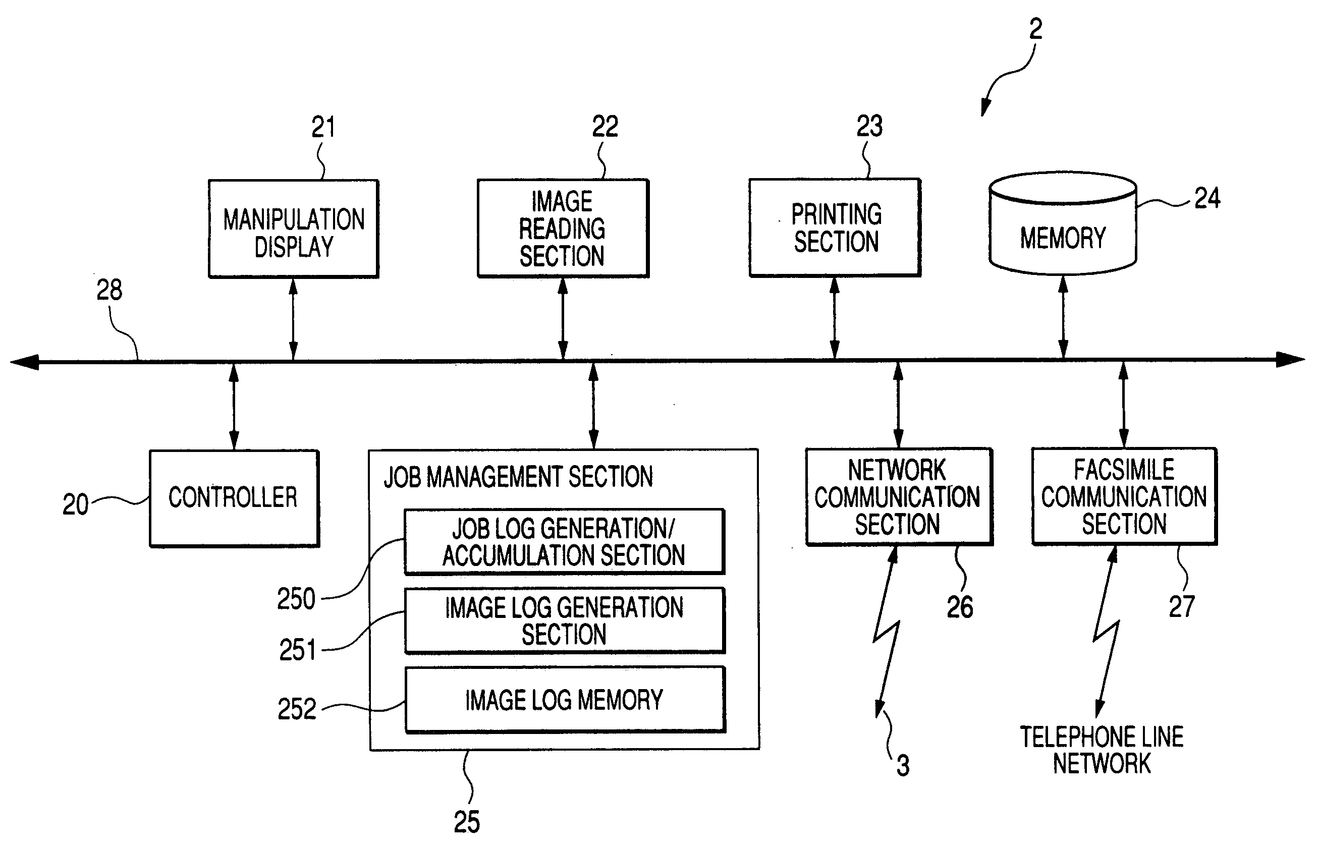
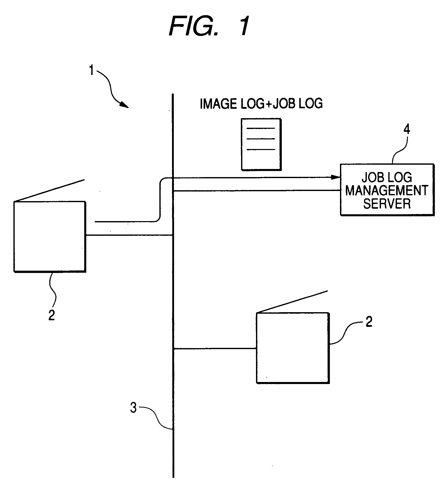
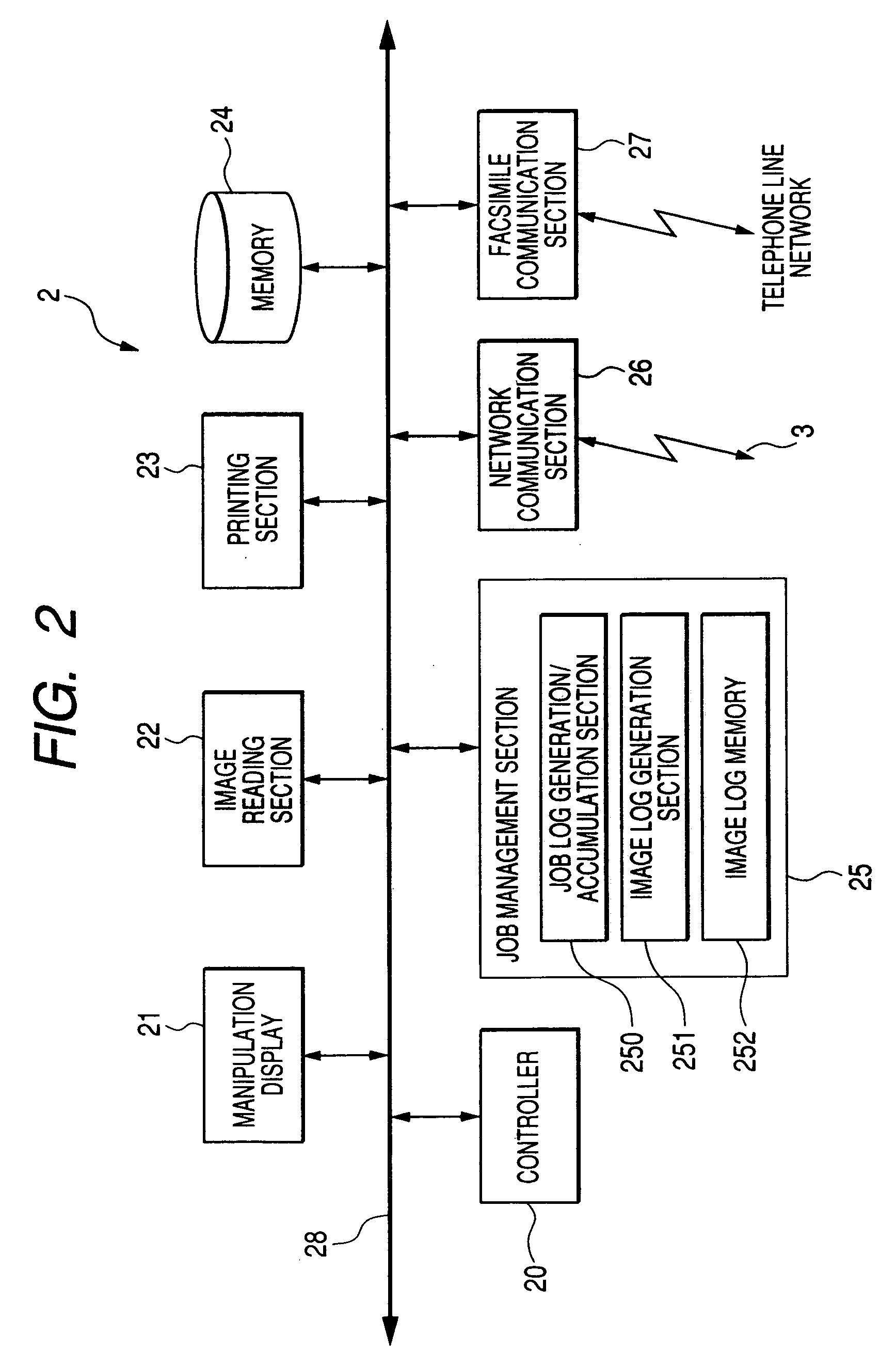
[0009] According to an aspect of the invention, a computer readable medium storing a program causing a computer to execute a function for displaying information on an image log, the function includes: generating an image log from an image which is used in processing a job, the job performed by an image processing apparatus; transferring the generated image log to a device that is connected to the image processing apparatus; generating information which includes status of at least one of the generating the image log or the transferring the image log; and displaying the generated information.

Problems solved by technology

However, in the conventional printing systems, since the printer is usually installed at a place that is distant from the clients, printed sheets may be stolen by a third person if they are left as they are.
However, it is difficult to prevent leakage of secret information by managing only job logs, because in that case a leakage source cannot be determined when leakage of a secret document has occurred.
However, since the generation and transfer of image logs take time, a long time elapses from the start to the end of a job and a job end time cannot be predicted, which lowers the ease of use of the printing system.

Method used


Image

  • Image log function display program, image log function display method, image processing apparatus, and image processing system
  • Image log function display program, image log function display method, image processing apparatus, and image processing system
  • Image log function display program, image log function display method, image processing apparatus, and image processing system

Examples


first exemplary embodiment

Operation of First Exemplary Embodiment

[0036] Next, the operation of this exemplary embodiment will be described for individual cases.

(1) Manager Setting Mode

[0037] A manager of the system 1 or each multifunction machine 2 inputs a password by manipulating the manipulation display 21 of the multifunction machine 2. If the manager is authenticated, a manager setting mode is established. The manager selects an “image log function setting” button in a menu picture and thereby causes the manipulation display 21 to display an image log function setting picture.

[0038] The manager makes an image log function on / off setting in the image log function setting picture. When the image log function setting picture is closed, the setting made in the image log function setting picture becomes effective. The controller 20 stores the thus-determined image log function setting information in the memory 24.

[0039] If a “close” button is depressed after selecting “image log function on,” the contro...

second exemplary embodiment

Operation of Second Exemplary Embodiment

[0052] Next, the operation of this exemplary embodiment will be described for individual cases.

(1) Manager Setting Mode

[0053] In this exemplary embodiment, settings of each multifunction machine 2 are made by a manager in the same manner as in the first exemplary embodiment.

(2) Ordinary Mode

[0054]FIG. 11 is a flowchart showing an ordinary-mode process of each multifunction machine 2 in the second exemplary embodiment. In an initial state, the controller 20 of the multifunction machine 2 causes the manipulation display 21 to display a menu picture. If a user selects a service in the menu picture, the controller 20 causes the manipulation display 21 to display a service details setting picture. The user sets service details in the service details setting picture. FIG. 11 corresponds to an exemplary case when copying is selected as a service. When the user depresses a start button, a copy job is started at step S2001. At step S2002, a docum...

third exemplary embodiment

Operation of Third Exemplary Embodiment

[0062] Next, the operation of this exemplary embodiment will be described for individual cases.

(1) Manager Setting Mode

[0063] A manager of the system 1 or each multifunction machine 2 inputs a password by manipulating the manipulation display 21 of the multifunction machine 2. If the manager is authenticated, a manager setting mode is established. The manager selects an “image log function setting” button in a menu picture and this causes the manipulation display 21 to display an image log function setting picture. The manager selects an image log function on / off setting in the image log function setting picture. When the image log function setting picture is closed, the setting made in the image log function setting picture becomes effective. The controller 20 stores the thus-determined image log function setting information in the memory 24.

[0064] After the image log function setting picture is closed, the controller 20 causes the manipul...


PUM


Abstract

A computer readable medium storing a program causing a computer to execute a function for displaying information on an image log, the function includes: generating an image log from an image which is used in processing a job, the job performed by an image processing apparatus; transferring the generated image log to a device that is connected to the image processing apparatus; generating information which includes status of at least one of the generating the image log or the transferring the image log; and displaying the generated information.

Description

[0001] This application claims priority under 35 USC 119 from Japanese patent document, JP2005-359206, the disclosure of which is incorporated by reference herein. BACKGROUND [0002] 1. Technical Field [0003] The present invention relates to an image log function display program, an image log function display method, an image processing apparatus, and an image processing system having a function of generating image logs from images that have been handled by a job in job log management which manages job logs (i.e., a job execution record) of copy jobs, print jobs, scanning jobs, facsimile jobs, etc. after they were carried out. [0004] 2 Related Art [0005] Printing systems are commonly known in which plural clients and a printer are connected to a LAN (local area network) and plural users can share the printer. [0006] In the above printing systems, a client generates print data of a document to be printed and the document can be printed by transmitting the print data to the printer whi...

Claims


Application Information

Patent Timeline
IPC IPC(8): G06F3/12
CPCG06F21/55G06F2221/2101
Inventor MAEKAWA, TAKAOSUZUKI, TETSUOMACHIDA, MASAHIRO
Owner FUJIFILM BUSINESS INNOVATION CORP
Learn More