Connection mode controlling apparatus, connection mode controlling method, and connection mode controlling program

Active Publication Date: 2007-06-14
BROTHER KOGYO KK +1
View PDF11 Cites 32 Cited by
  • Summary
  • Abstract
  • Description
  • Claims
  • Application Information

AI Technical Summary

Benefits of technology

[0033] According to the invention of claim 13, the computer functions so that a main path and a sub path are formed so as to connect a plurality of relays to one relay, the distribution information distributed via the main path is used for an external output process in the one relay and for distribution to another relay belonging to a hierarchical level lower than the one relay, and the distribution i

Problems solved by technology

Consequently, a problem occurs such that the storage amount in the buffer gradually decreases and, in some cases, the contents reproducing process in the lower-order nodes is interrupted.
The interrup

Method used


Image

  • Connection mode controlling apparatus, connection mode controlling method, and connection mode controlling program
  • Connection mode controlling apparatus, connection mode controlling method, and connection mode controlling program
  • Connection mode controlling apparatus, connection mode controlling method, and connection mode controlling program

Examples


first embodiment

(I) First Embodiment

(A) Embodiment

[0061] A first embodiment according to the present invention will be described first with reference to FIG. 1 to FIGS. 8A and 8B.

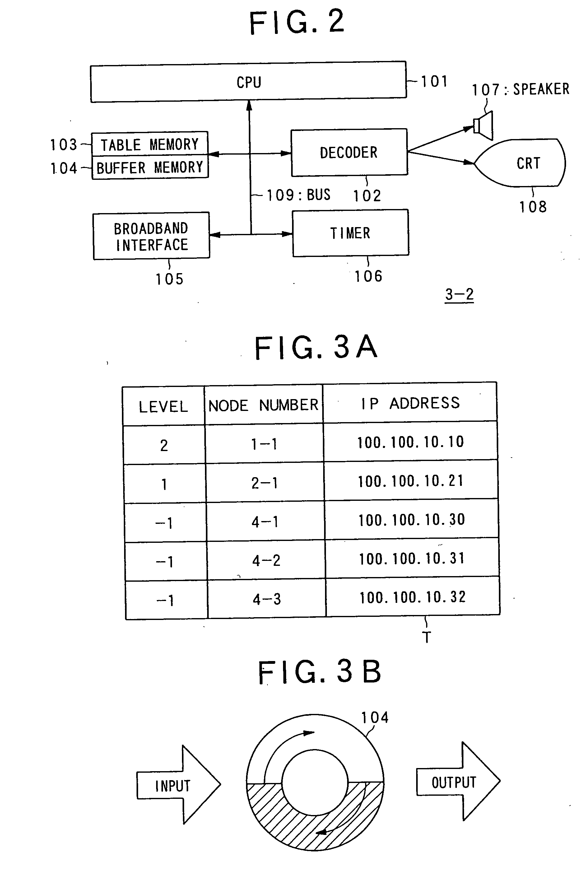
[0062]FIG. 1 is a block diagram showing a schematic configuration of a network system according to a first embodiment. FIG. 2 is a block diagram showing a general configuration of a node included in the network system. FIGS. 3A and 3B are diagrams showing a detailed configuration of the node. FIG. 4 is a flowchart showing normal distributing operation in the network system. FIG. 5 is a block diagram showing a schematic configuration of the network system after the relay function in part of the nodes stops. FIGS. 6A, 6B, and 6C are a flowchart showing operations in a lower-order node when the relay function stops. FIG. 7 is a diagram showing operations of a lower-order node when the relay function stops. FIGS. 8A and 8B are diagrams showing operation in a network system according to a modification of the first embodiment...

second embodiment

(II) Second Embodiment

[0126] A second embodiment as another embodiment according to the present invention will now be described with reference to FIGS. 9 to 12.

[0127]FIGS. 9 and 10 are block diagrams each showing a schematic configuration of a network system according to the second embodiment, and FIGS. 11 and 12 are flowcharts showing operations of the network system.

[0128] In the foregoing first embodiment, the case where the relay function in a node stops during reception of contents distributed via only one line L has been described. In the second embodiment described below, one node is preliminarily provided with two paths; a main path and a sub path and receives distributed contents.

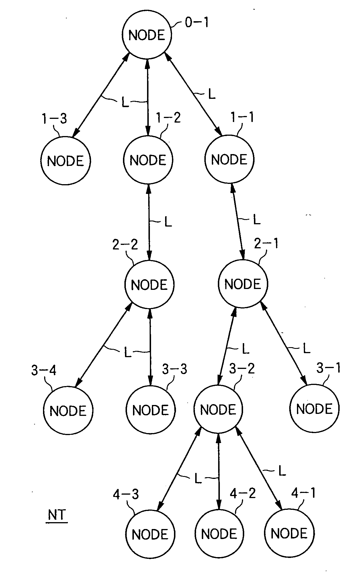
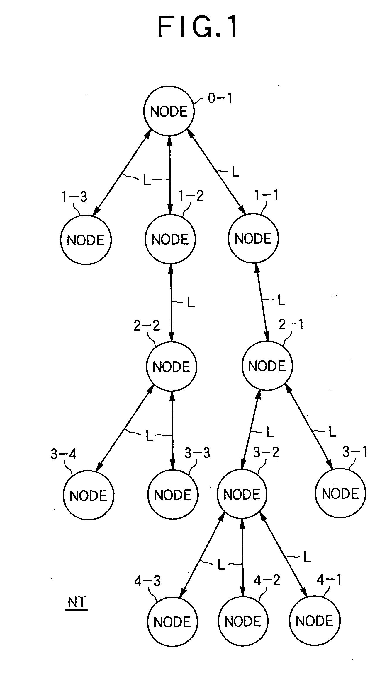
[0129] As shown in FIG. 9, in a manner similar to the first embodiment, a network system NT2 according to the second embodiment is formed by a tree structure whose apex is the node 0-1 as a distributing apparatus. The network system NT2 includes the nodes 1-1, 1-2, and 1-3 as nodes constructing ...


PUM


Abstract

There is provided a network control device capable of surely distributing a content even when a relay function of one of the nodes contained in a network stops, without affecting the process in nodes below the node and while improving the re-liability of the network system itself. When controlling a node contained in a network system including a server and a plurality of nodes constituting a plurality of hierarchies and connected to one another, wherein a content is distributed from the server to the respective nodes, it is checked whether a content relay function in a node located at the uplink with respect to the node in the content distribution has stopped. When the stop of the relay function is detected, control is performed so that the consumption speed of the content accumulated in the lower node in the process executed in the node is smaller than the consumption speed before the relay function has stopped.

Description

BACKGROUND OF THE INVENTION [0001] 1. Field of the Invention [0002] The present invention relates to a technical field of a network controlling apparatus, a connection mode controlling apparatus, a network controlling method, a connection mode controlling method, a network controlling program, and a connection mode controlling program. More specifically, the invention relates to a technical field of a network controlling apparatus, a connection mode controlling apparatus, a network controlling method, a connection mode controlling method, a network controlling program, and a connection mode controlling program for controlling a distribution mode of distributing distribution information distributed from a distribution source in a network system while stepwisely relaying the distribution information in a relay unit which is connected while constructing a hierarchy of a plurality of levels. [0003] 2. Discussion of the Related Art [0004] In recent years, as the speed of the Internet lin...

Claims


Application Information

Patent Timeline
IPC IPC(8): H04L12/54H04L69/40
CPCH04L47/10H04L47/25H04N21/23406H04N21/44004H04N21/6125H04N21/64746H04L67/1002H04L67/1001
Inventor HIBINO, YOSHIHIKOKIYOHARA, YUJISUZUKI, HIROAKIUSHIYAMA, KENTAROIIJIMA, KOICHI
Owner BROTHER KOGYO KK
Why Eureka
Try Eureka