

Apparatus and method for measuring at least one of arrangement and shape of shots on substrate, exposure apparatus, and device manufacturing method
a technology of exposure apparatus and substrate, which is applied in the direction of optics, instruments, image enhancement, etc., can solve the problems of inability to achieve a sufficient accuracy, and inability to adjust the angle of the shot, etc., to achieve high accuracy and high throughput
- Summary
- Abstract
- Description
- Claims
- Application Information
AI Technical Summary
Benefits of technology
Problems solved by technology
Method used
Image

Examples
first embodiment
[0051] A technique which is cited in problem (i) and causes an apparatus to automatically select an optimal algorism without exposing the lot will be explained below as the first embodiment.
[0052]FIG. 3 is a schematic view showing an off-axis wafer alignment system in a reduction projection exposure apparatus according to this embodiment.
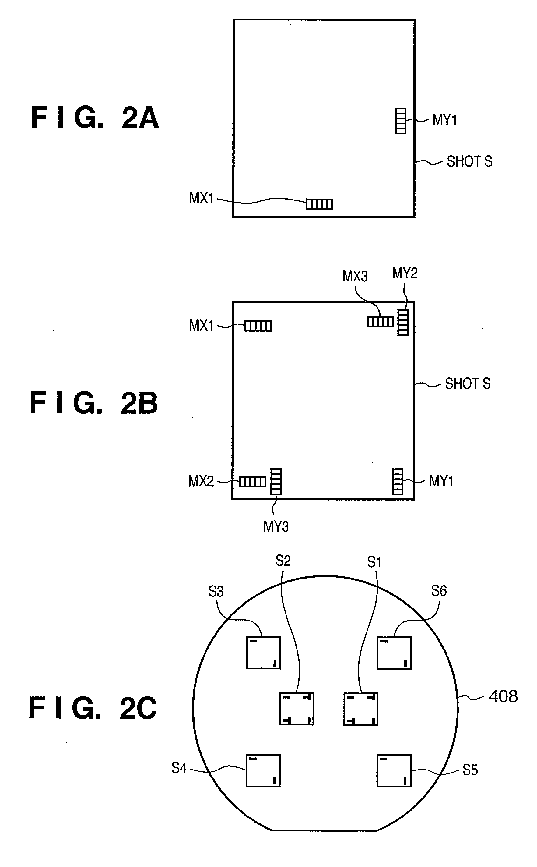
[0053] Referring to FIG. 3, reference numeral 401 denotes a reticle; 402, a projection optical system; and 403, an image storing and calculating device which executes various image calculation processes for an input image signal, and stores the image signal and processing result. A pre-alignment device 406 coarsely adjusts the orientation of a wafer from its contour criterion when a wafer loading device (not shown) feeds the wafer to an alignment system. A computer terminal 407 accepts a command input by a user. A wafer 408 serves as an alignment target. A microscope 404 allows an operator to observe a pattern image formed on the wafer 408 while e...
second embodiment
[0081] A technique which is cited in problem (ii) and satisfactorily processes a lot having changed non-linear error components will be explained below as the second embodiment.
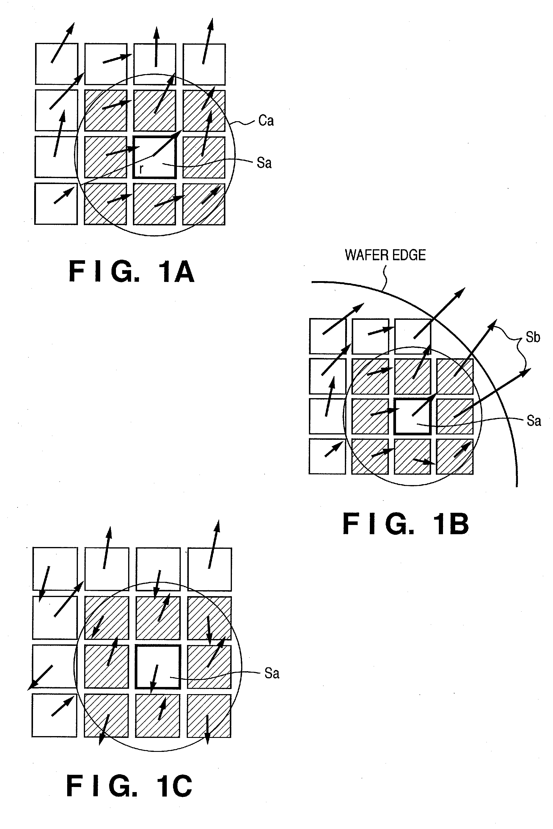
[0082] Assume, for example, a lot as shown in FIG. 8C which includes a mixture of wafers having locally large non-linear errors as shown in FIG. 8A and wafers having errors that occur depending on the scan direction as shown in FIG. 8B. A process for determining the intervals of wafers having a tendency shown in FIG. 8A and those of wafers having a tendency shown in FIG. 8B in the lot will be explained.
[0083]FIG. 9 is a flowchart showing a process for determining an optimal non-linear correction condition for each cluster according to this embodiment.
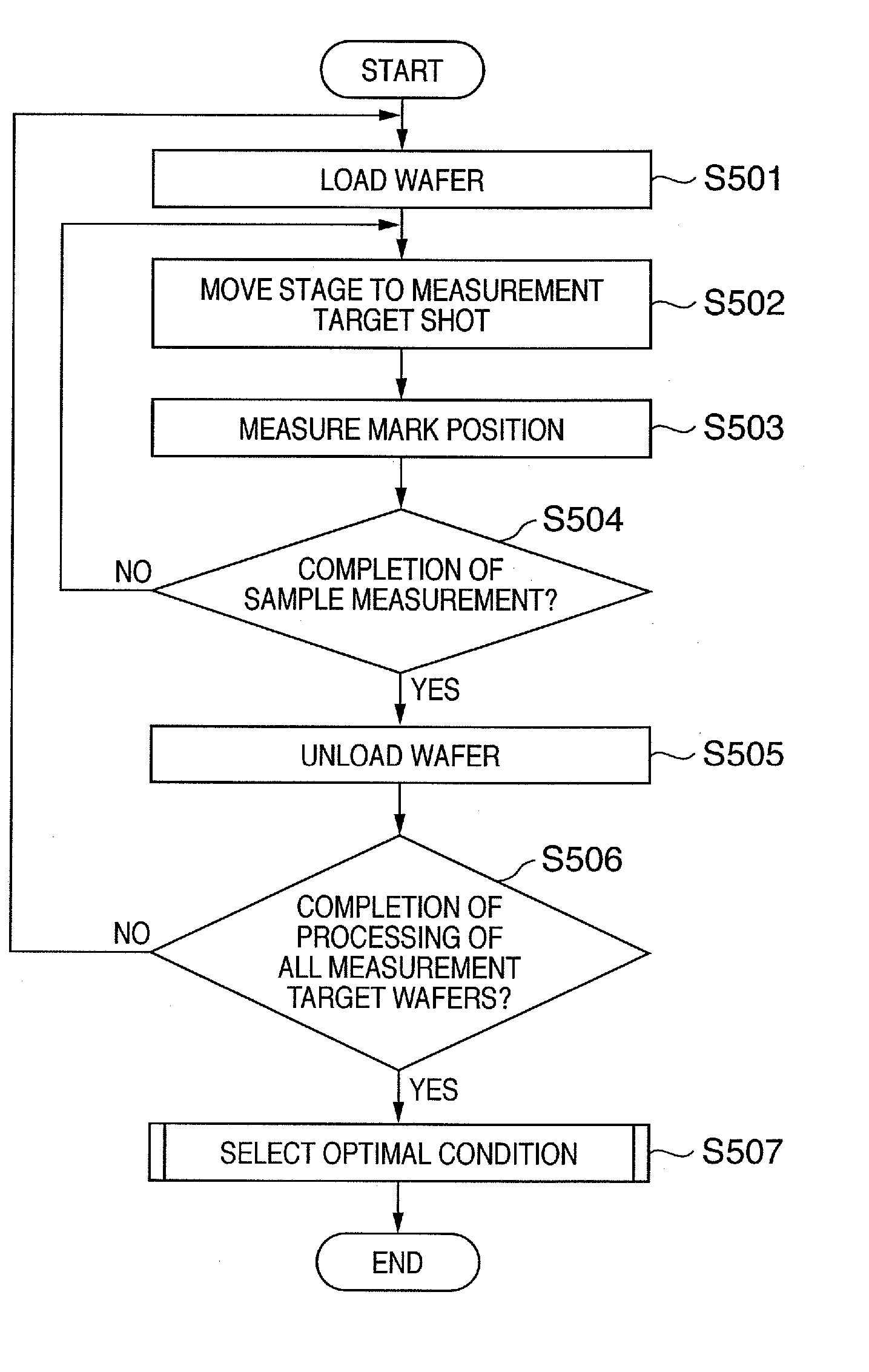
[0084] Referring to FIG. 9, in step S1001, the displacement amounts of a large number of shots of all wafers in the target lot are measured, like the processes in steps S501 to S506 shown in FIG. 4 according to the first embodiment. A measurement result table ...
third embodiment
[0101] The first and second embodiments have been described with reference to the case wherein an exposure apparatus executes alignment measurement using its microscope and image storing and calculating device. However, a measurement device outside the exposure apparatus may be used. An external measurement device which is called an overlay measurement device and measures an exposure result comprises a similar microscope or image storing and calculating device. Processing, using the above methods, an alignment measurement result measured by this external measurement device and feeding back the processed result as correction data during exposure makes it possible to obtain a satisfactory alignment measurement result, like the first and second embodiments.
[0102] According to the above-described embodiments, an optimal non-linear correction condition can be automatically determined based on the stability index of a non-linear error component in a lot.
[0103] Even when a non-linear err...
PUM
 Abstract
Description
Claims
Application Information