
Piston compressor

Inactive Publication Date: 2007-06-14
TOYOTA IND CORP
View PDF3 Cites 0 Cited by
  • Summary
  • Abstract
  • Description
  • Claims
  • Application Information

AI Technical Summary

Benefits of technology

[0012] It is an objective of the present invention to provide a piston compressor that is capable of preventing a reduction in volume efficiency while inhibiting leakage of the refrigerant.

Problems solved by technology

Moreover, it has been disclosed in the Prior Art section of Japanese Laid-Open Patent Publication No. 9-4563 that, by increasing the thickness of the valve plate, the degree of rigidity of the valve plate can be reinforced in such a way that, even if the valve plate is subjected to a compression reaction force, the valve plate is not easily deformed.
This demonstrates that the performance of the piston compressor is diminished.
As a result, the degree of sealing force between the cylinder block and the valve plate is reduced, and such a situation is not desirable.
However, as demonstrated by the straight line M of FIG. 4, increasing the thickness of the valve plate results in an increase in dead volume and thus reduces the volume efficiency of the compressor.

Method used


Image

  • Piston compressor
  • Piston compressor
  • Piston compressor

Examples


Embodiment Construction

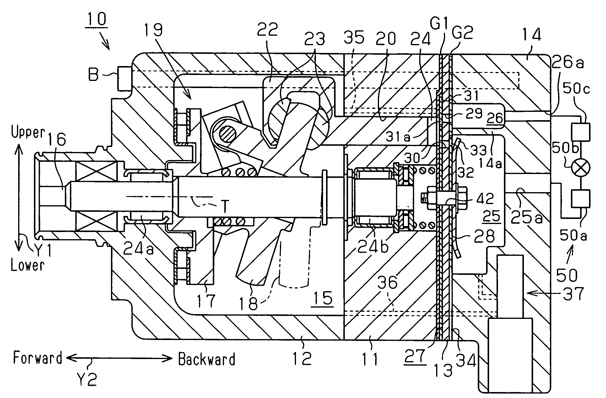
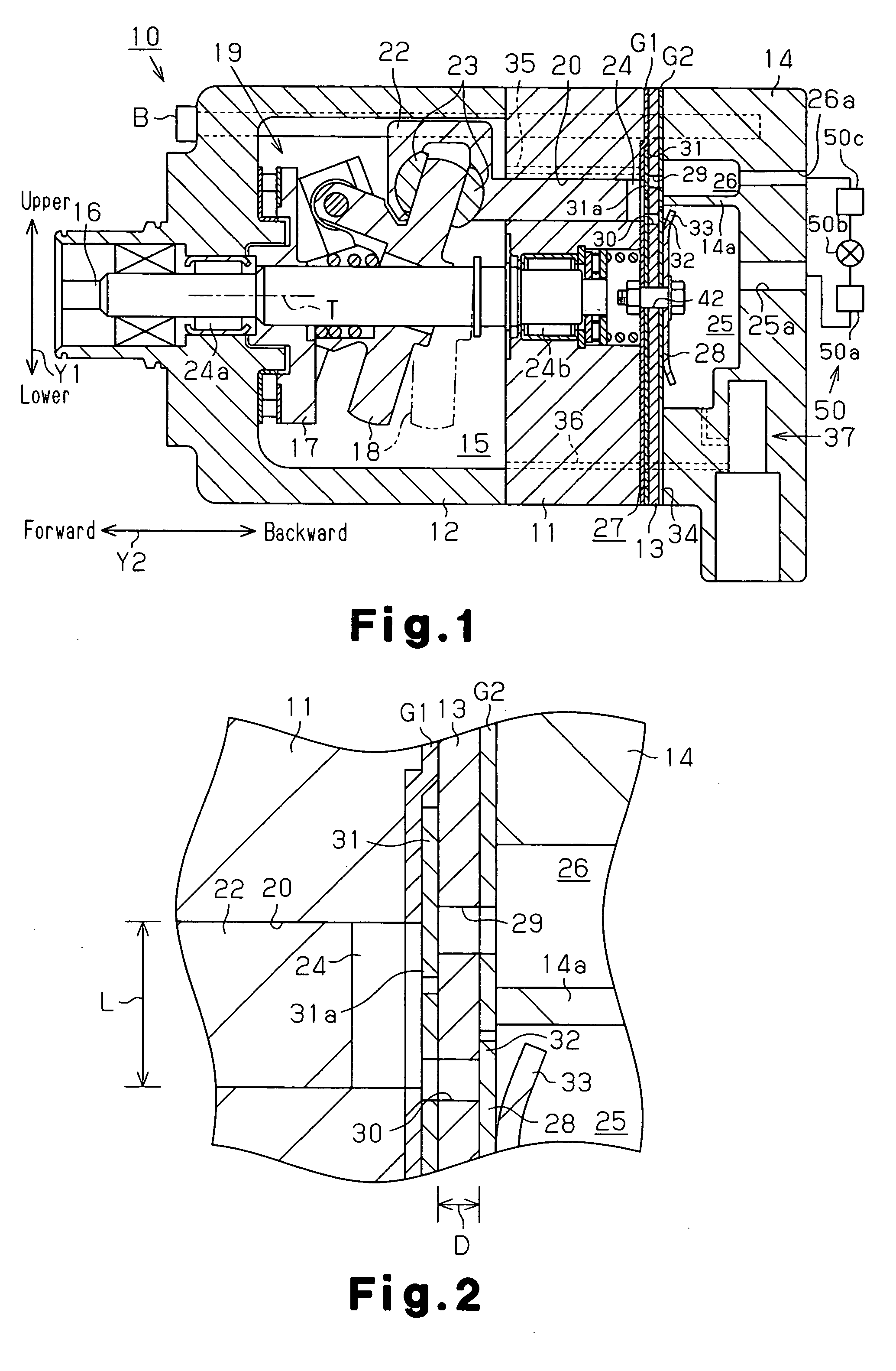
[0020] The present invention will now be described with reference to FIG. 1 to FIG. 3 and to an embodiment of a piston compressor for use in a refrigeration circuit in which carbon dioxide is used as a refrigerant. In the following description, with respect to the “upward” and “downward” directions of the piston compressor, the direction of arrow Y1 appearing in FIG. 1 is defined as a vertical direction, and the “frontward” and “rearward” directions of the piston compressor are each defined as a direction of arrow Y2.

[0021] As illustrated in FIG. 1, an entire housing of a piston compressor 10 includes: a cylinder block 11; a front housing member 12 fixed to a front end of the cylinder block 11; and a rear housing member 14 fixed to a rear end of the cylinder block 11 by way of a valve plate 13. As illustrated in FIG. 2, a first gasket G1 that serves as a sealing member is interposed between a rear end face of the cylinder block 11 and a front face of the valve plate 13. The first g...


PUM


Abstract

A piston compressor in which carbon dioxide is used as a refrigerant is provided. The compressor includes a cylinder block, reciprocating pistons, a valve plate, a housing member, and sealing members. The cylinder block has an end face and a plurality of cylinder bores. The pistons are housed in the individual cylinder bores. The valve plate has a plurality of discharge ports. The housing member is fixed to the end face of the cylinder block with the valve plate in between. The housing member has a partition wall. The housing member and the valve plate define a suction chamber and a discharge chamber. The discharge chamber is connected to the cylinder bores through the corresponding discharge ports. The suction chamber and the discharge chamber are partitioned by the partition wall. The sealing members each are interposed between the valve plate and the cylinder block, and between the valve plate and the housing. A value of a ratio of the thickness of the valve plate relative to a diameter of each cylinder bore is between 0.13 and 0.4, inclusive.

Description

BACKGROUND OF THE INVENTION [0001] The present invention relates to a piston compressor in which sealing members are interposed between a valve plate and a cylinder block, and between a valve plate and a housing member. [0002] In general, in a piston compressor configuring a refrigeration circuit of a vehicle air conditioner device, an entire housing includes: a cylinder block; a front housing member fixed on a front end face of the cylinder block; and a rear housing member fixed onto a rear end face of the cylinder block with a valve plate in between. In addition, the entire housing is integrated by tightening and fixing the front housing member, the cylinder block, the valve plate, and the rear housing member to one another by means of a plurality of through bolts. In the cylinder block, a plurality of cylinder bores are arranged around a shaft, and a piston is housed so as to be able to reciprocate in each cylinder bore. Moreover, in each cylinder bore, a compression chamber, who...

Claims


Application Information

Patent Timeline
IPC IPC(8): F04B27/08
CPCF04B27/1009F04B27/1081F04B39/1066
Inventor ENOKIJIMA, FUMINOBUFUKANUMA, TETSUHIKOYOKOMACHI, NAOYAINOUE, MASAKISUMIKAWA, SHUN
Owner TOYOTA IND CORP
Features
  • Generate Ideas
  • Intellectual Property
  • Life Sciences
  • Materials
  • Tech Scout
  • Unparalleled Data Quality
  • Higher Quality Content
  • 60% Fewer Hallucinations
Learn More