Compression apparatus

a compression device and compression tube technology, applied in non-surgical orthopedic devices, physical therapy, massage, etc., can solve the problems of increasing patient discomfort, swelling (edema) and tissue breakdown, and high pressure in the veins of the lower leg

Active Publication Date: 2007-06-14
KPR U S LLC
View PDF99 Cites 105 Cited by
  • Summary
  • Abstract
  • Description
  • Claims
  • Application Information

AI Technical Summary

Benefits of technology

[0011] In one embodiment, the compression apparatus includes a foot sleeve for applying compressive forces to a patient's foot. The foot sleeve includes an inflatable member disposed therewithin, the inflatable member being freely movable in relation to the foot sleeve. The foot sleeve includes a contact layer and an outer layer. The contact layer and the outer layer are fixedly joined by radio frequency (RF) welding, or by other suitable methods, along their corresponding perimeters thereby defining a space therebetween. The outer surface of the contact layer contacts the bottom portion of the foot and it may be fabricated from a chemically treated material having a mesh-like fabric with wicking ability. The outer layer may be fabricated from a laminated material having a soft material for cushioning effect against the skin. In addition, the outer layer provides the attachment surface for the hook and loop features.

Problems solved by technology

Patients who develop this condition often have swelling (edema) and tissue breakdown (venous stasis ulcer) in the lower leg.
When a DVT occurs, the valves that are located within the veins of the leg can be damaged, which in turn can cause stasis and high pressure in the veins of the lower leg.
Some prior art devices are bulky and may irritate portions of the limb undergoing treatment which may increase patient discomfort and may increase the possibility that the patient may not complete the treatment regimen.

Method used


Image

  • Compression apparatus
  • Compression apparatus
  • Compression apparatus

Examples


Embodiment Construction

[0025] With reference to the drawing figures, in which like references numerals identify identical or corresponding elements, various embodiments of the presently disclosed compression apparatus will now be described in detail.

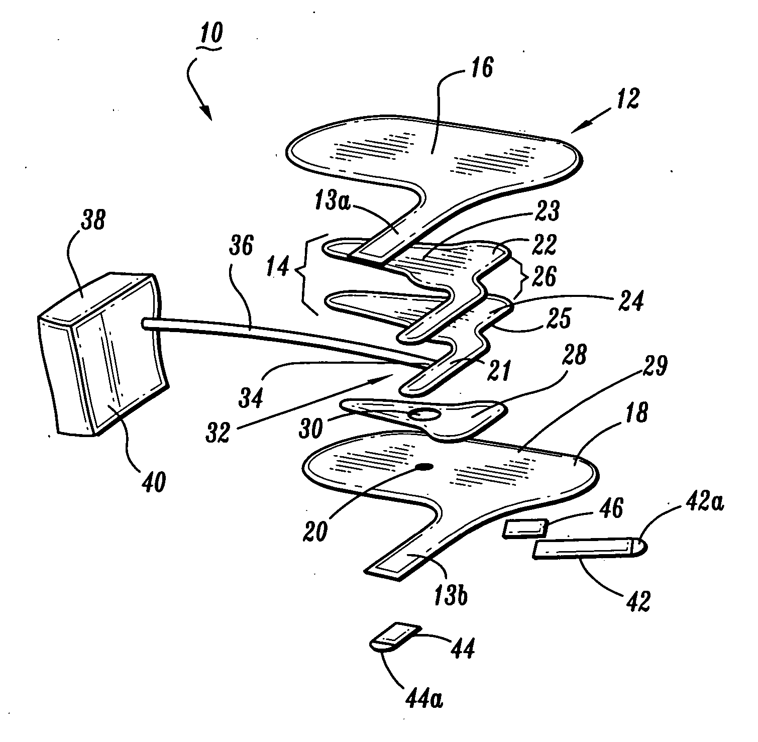
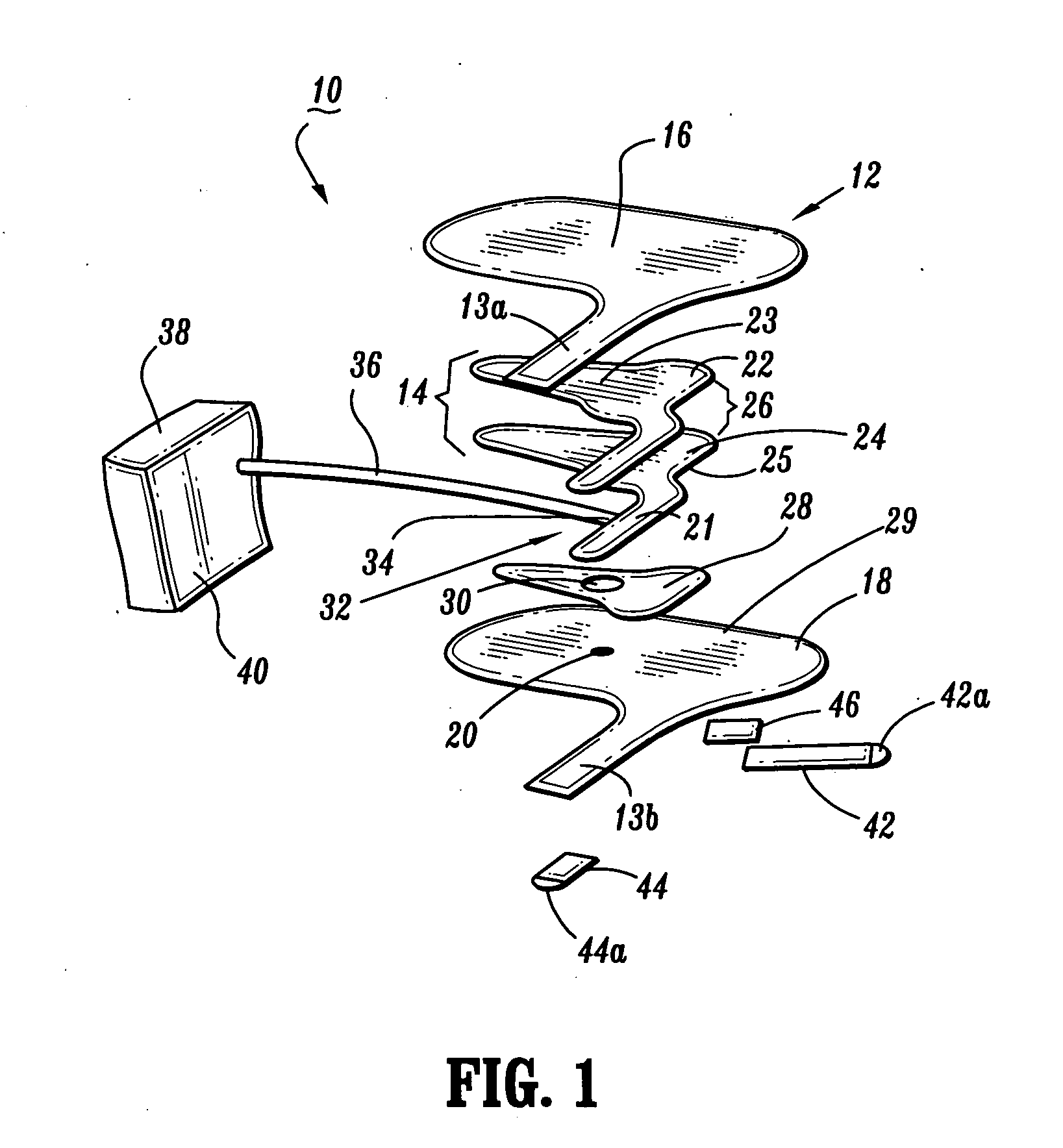
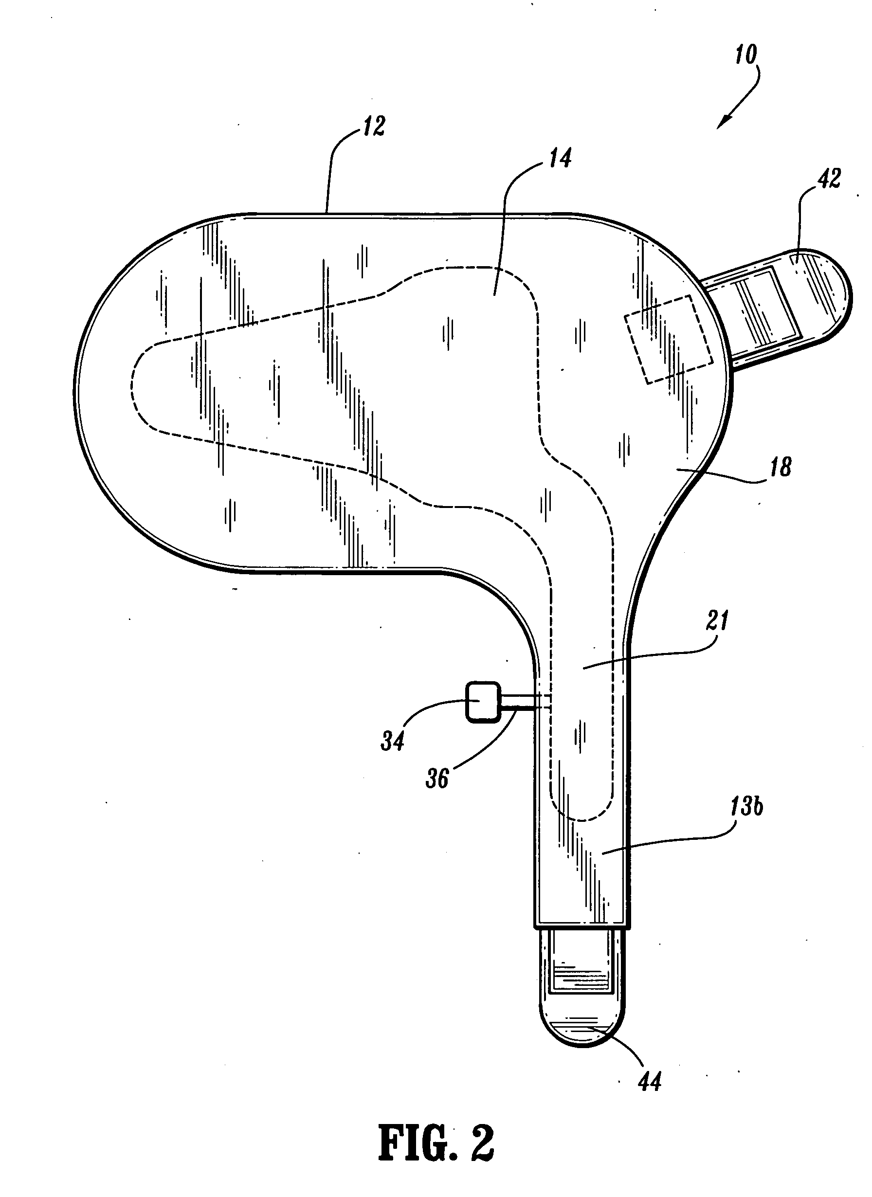
[0026] With initial reference to FIGS. 1-4, a first embodiment of a compression apparatus in accordance with the present disclosure is illustrated and is designated generally as compression apparatus 10. Compression apparatus 10 is adapted for use in a system for applying compressive pressure to a portion of a body, such as, for example, a foot of a person. Compression apparatus 10 generally includes a foot sleeve 12 configured for disposal about a foot and an inflatable member 14 disposed within foot sleeve 12 and being freely movable or repositionable in relation to foot sleeve 12. Moreover, foot sleeve 12 is configured and dimensioned for disposing about the right or left foot of the subject.

[0027] Foot sleeve 12 includes a contact layer 16 and an outer l...


PUM


Abstract

A compression apparatus is described having a sleeve and an inflatable member disposed within the sleeve, the inflatable member being movable in relation to the sleeve. The compression apparatus includes a hook and loop features attached to the foot sleeve for securing compression apparatus to the feet.

Description

BACKGROUND [0001] 1. Technical Field [0002] The present disclosure relates generally to compression apparatus. In particular, the present disclosure relates to a compression apparatus configured for applying compressive forces to a portion of a patient's anatomy. [0003] 2. Description of the Related Art [0004] Compression devices for applying compressive forces to a selected area of a person's anatomy are generally employed to improve blood flow in the selected area. Compression devices that provide intermittent pulses of a compressed fluid (i.e. air) to inflate at least one inflatable chamber in a sleeve are particularly useful. This cyclic application of pressure provides a non-invasive method of prophylaxis to reduce the incidence of deep vein thrombosis (DVT), and the like. These compression devices find particular use during surgery on patients with high-risk conditions such as obesity, advanced age, malignancy, or prior thromboembolism. Patients who develop this condition ofte...

Claims


Application Information

Patent Timeline
Patent Type & Authority Applications(United States)
IPC IPC(8): A61H19/00
CPCA61H9/0078A61H2205/12A61H2201/1697A61H2209/00A61F13/06
Inventor MEYER, ANN
Owner KPR U S LLC
Why Eureka
Try Eureka