
Peeling member and peeling device

a peeling device and peeling technology, applied in the field of peeling members, can solve the problems of poor peeling performance, poor peeling performance, and inability to obtain excellent quality images, and achieve the effects of preventing jamming of thick paper, excellent peeling performance, and low cos

Inactive Publication Date: 2018-12-27
NTN CORP
View PDF0 Cites 1 Cited by
  • Summary
  • Abstract
  • Description
  • Claims
  • Application Information

AI Technical Summary

Benefits of technology

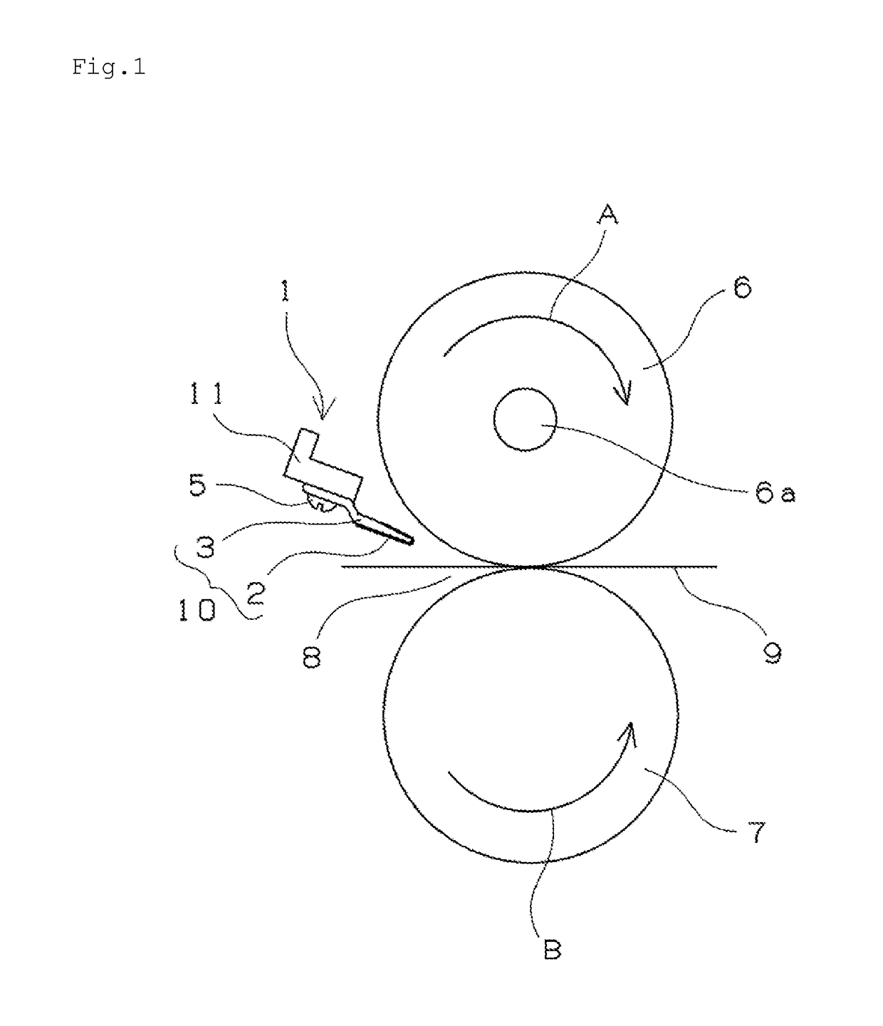
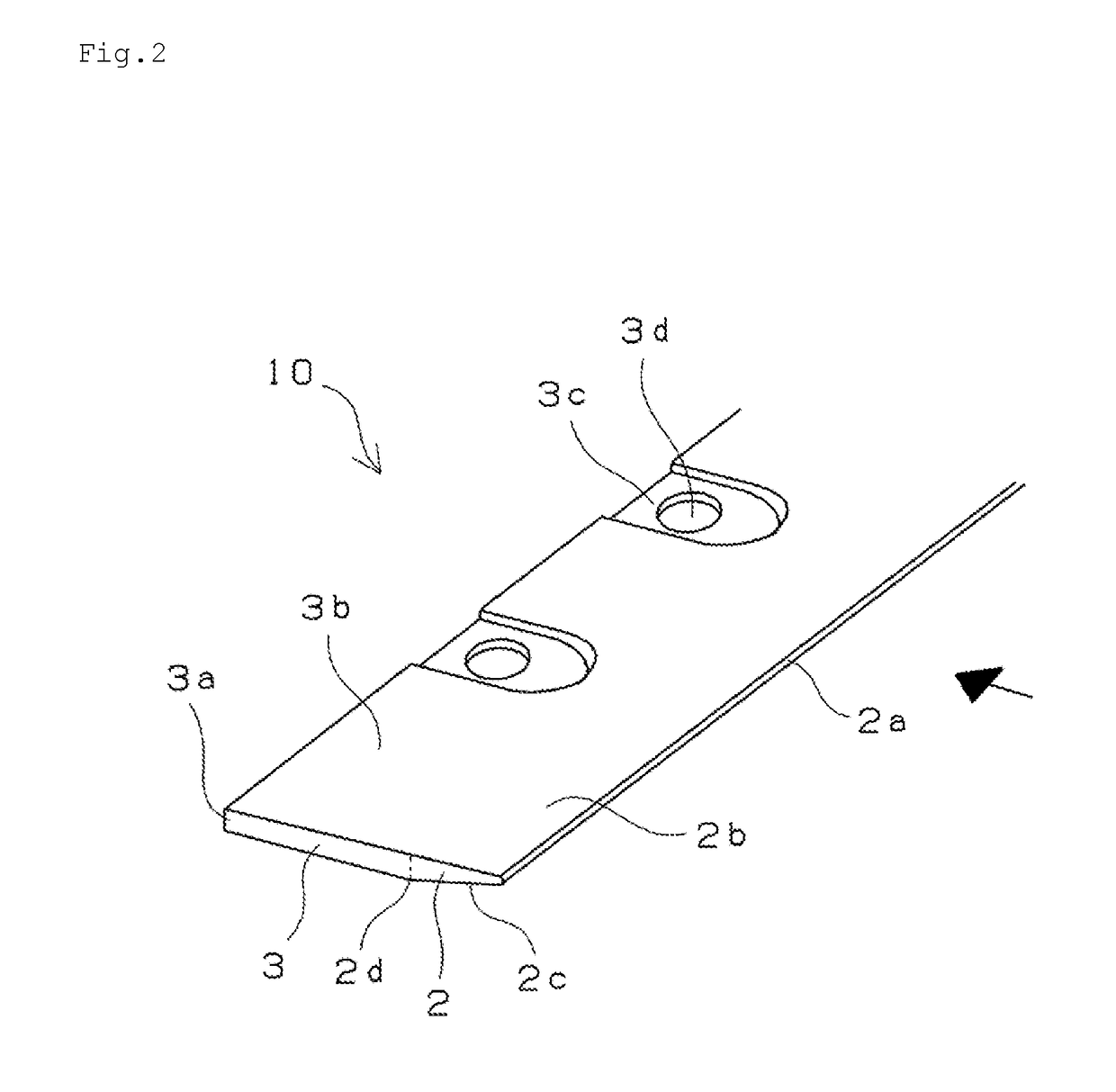
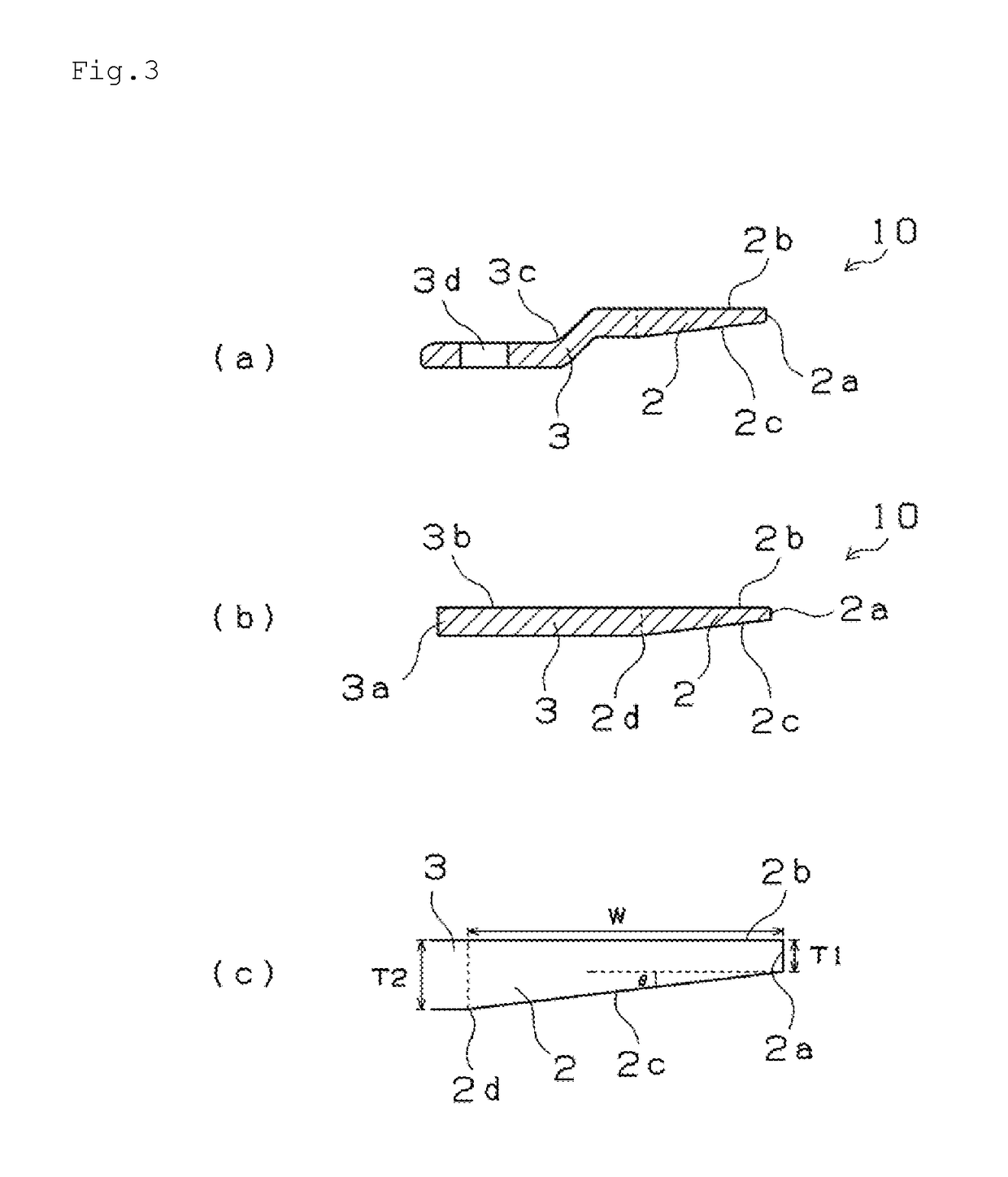
The present invention is a peeling member for an electronic photographic device that includes a peeling sheet for peeling paper from a roller. The peeling sheet is inclined against the roller at a predetermined angle to allow for easy insertion into narrow spaces between the rollers or belts. The peeling sheet is made of a thin metal plate with a thin peeling portion and a thick support portion, and has a flat surface continuous with the support portion for efficient peeling. The peeling portion has an inclined surface close to the roller to prevent deformation caused by paper jamming. The peeling device also includes the roller of the electronic photographic device and the peeling member, which ensures smooth peeling and prevents spattering or waving. The peeling sheet is firmly stuck to the peeling portion using a non-adhesive resin film that prevents toner adhering and achieves low friction performance with paper. The non-adhesive resin film is made of a fluororesin film that is highly resistant to toner adhering.

Problems solved by technology

Since the separation claw is contacted with the roller in part, the roller is partially worn and an excellent quality image cannot be obtained.
Further, since the separation claw is also contacted with a paper in part, the developing agent transferred to the paper is scraped easily, and therefore the paper might be get dirt due to the scraped developing agent stuck to the separation claw.

Method used


Image

  • Peeling member and peeling device
  • Peeling member and peeling device
  • Peeling member and peeling device

Examples


example

Example 1

[0053]A peeling member was manufactured by processing a distal end portion into a tapered shape by means of machine processing after processing a stainless (SUS304CSP) coil having a thickness of 1.5 mm into a predetermined size by using a progressive press die. The manufacturing process is described with reference to FIG. 8. FIG. 8 is a schematic view of the manufacturing process. The processes (A) to (F) show a schematic order of the process. At first, a steel plate 20 shown in the process (A) is punched into an external size of the peeling sheet by using a press die. Next, the recess portions 3c are formed by means of drawing processing as shown in the process (B). Next, the bolt holes 3d for bolt fixing are punched by using a press die as shown in the process (C). And then, the drawn portion is cut into a predetermined size as shown in the process (D). After that, a peeling sheet 10′ before forming a tapered portion is punched from the steel plate 20 as shown in the proc...

example 2

[0056]Similar to the example 1, a peeling member was manufactured by processing a distal end portion by machine processing such that a thickness of the distal end portion became 0.3 mm after processing a stainless (SUS304CSP) coil having a thickness of 1.5 mm into a predetermined size by using a progressive press die. A punching process using the press die is shown by the order of the processes (A) to (E) in FIG. 8. After the processing using the press die, a peeling sheet 10′ is punched from a steel plate 20. And then, a tapered distal end portion formed by means of machine processing such that an opposite paper passing side opposite to a drawn portion is grinded into a tapered shape is cut in a longitudinal direction by means of pressing so as to enhance the precision of straightness as shown in the process (F), so that the peeling sheet 10 having a peeling portion 2 and a support portion 3 is obtained. The peeling sheet 10 has a thickness of the most distal end portion of 0.3 mm ...


PUM


Abstract

To provide a peeling member capable of suppressing a waving phenomenon of a peeling sheet, contacting linearly with a roller sufficiently, preventing deformation due to jamming of a paper and showing excellent paper peeling performance, and to provide a peeling device provided with the peeling member . The peeling member includes a peeling sheet 10 that peels a paper from a fixing roller 6 of an electronic photographic device. The peeling sheet 10 is formed of one metal plate, the peeling sheet 10 including a peeling portion 2 that forms the distal end portion, and a support potion 3 that is thicker than the peeling portion 2. The peeling portion 2 is arranged at one long side of the metal plate such that a paper passing surface 2b of the peeling portion 2 is formed as a flat surface continued to a surface of the support portion 3 and an opposite paper passing surface of the peeling portion 2 is formed as an inclined surface 2c inclined against the paper passing surface 2b such that a thickness of the peeling portion 2 is increased from a most distal end portion 2a of the peeling portion 2 toward a boundary portion 2d the peeling portion 2 and the support portion 3. The inclined surface 2c is arranged at a side of the fixing roller 6. A distance D1 between the most distal end portion 2a and the roller and a distance D2 between the boundary portion 2d and the roller fulfil a relation of D1≤D2≤5×D1.

Description

TECHNICAL FIELD[0001]The present invention relates to a peeling member that peels a paper from various types of rollers arranged in an electronic photographic device such as a copying machine and a laser printer, in particular relates to a peeling member for a fixing member such as a fixing roller. Further, the present invention relates to a peeling device provided with the peeling member.BACKGROUND ART[0002]In an electronic photographic device such as a copying machine and a laser printer, various types of rollers that develop an electrostatic latent image, which is formed on a photoreceptor drum, on a paper by using a developing agent such as toner and then fixes the developed image is arranged. In a developing portion, the photoreceptor drum and an oil coating roller except in a dry type electronic photo graphic are arranged, and in the fixing portion, a fixing roller and a pressing roller are arranged. Conventionally, in a photoreceptor drum, a fixing roller or a pressing roller...

Claims


Application Information

Patent Timeline
Patent Type & Authority Applications(United States)
IPC IPC(8): G03G15/00G03G15/20G03G15/02G03G15/06G03G15/16
CPCG03G15/6532G03G15/2053G03G15/02G03G15/06G03G15/16G03G15/2028G03G15/14G03G2215/2093
Inventor HIROSE, KAZUO
Owner NTN CORP
Learn More