Electromechanical force-magnitude, force-angle sensor

a force angle and magnetometer technology, applied in the field of force sensors, can solve the problems of single-axis sensor difficulty, force angle error, force angle extraction from multiple sensors, etc., and achieve the effect of superior user feedback

Active Publication Date: 2007-06-21
WISCONSIN ALUMNI RES FOUND
View PDF14 Cites 53 Cited by
  • Summary
  • Abstract
  • Description
  • Claims
  • Application Information

AI Technical Summary

Benefits of technology

[0006] The present invention provides an electromechanical force angle, force magnitude sensor using an eccentrically rotating mechanical element to detect the force angle. A single axis sensor, such as a strain gauge, mounted on the rotating element is always aligned

Problems solved by technology

Extraction of force angle from multiple, single-axis sensors is difficult, requiring accurate alignment and calibration of multiple sensors.
Fu

Method used


Image

  • Electromechanical force-magnitude, force-angle sensor
  • Electromechanical force-magnitude, force-angle sensor
  • Electromechanical force-magnitude, force-angle sensor

Examples


Embodiment Construction

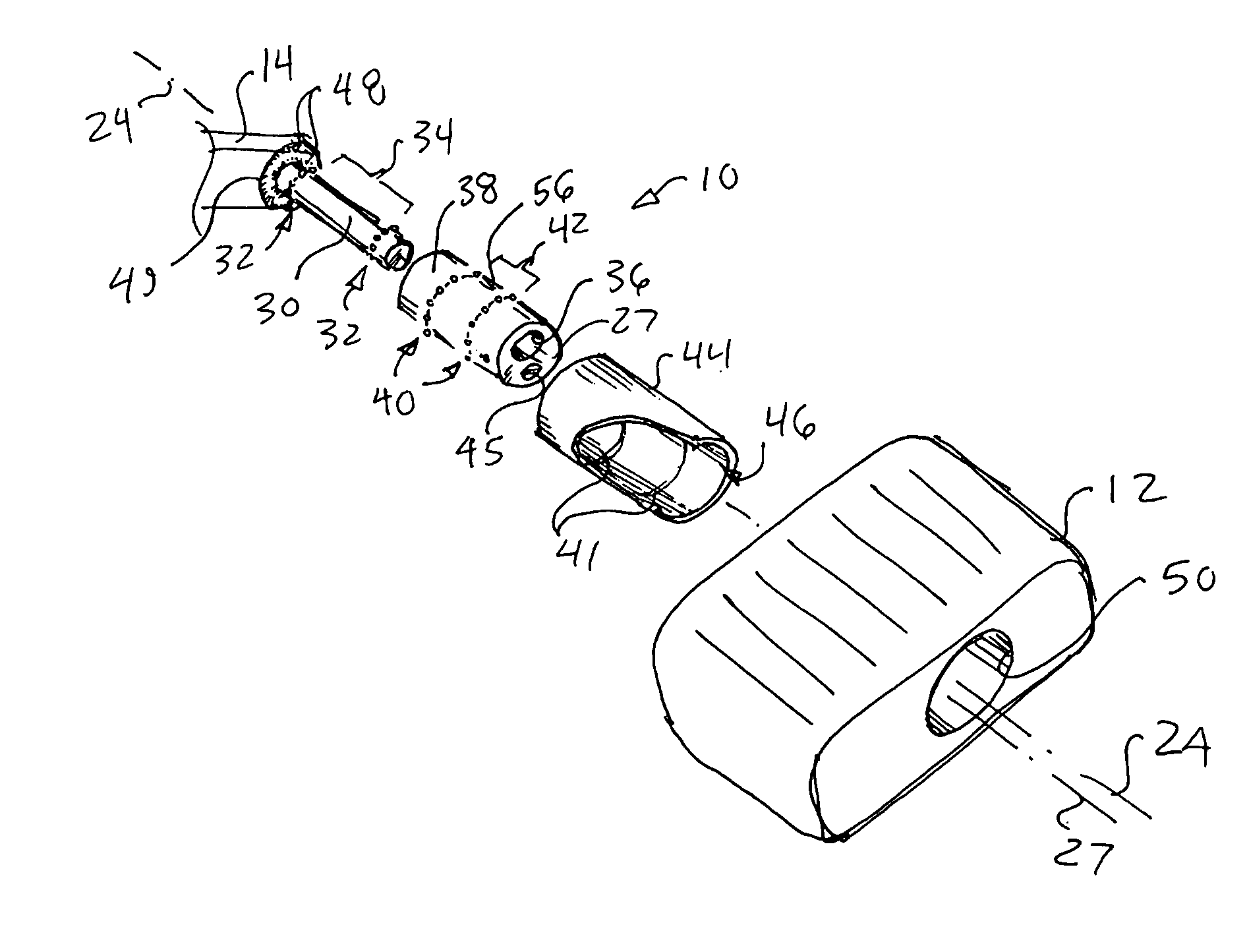
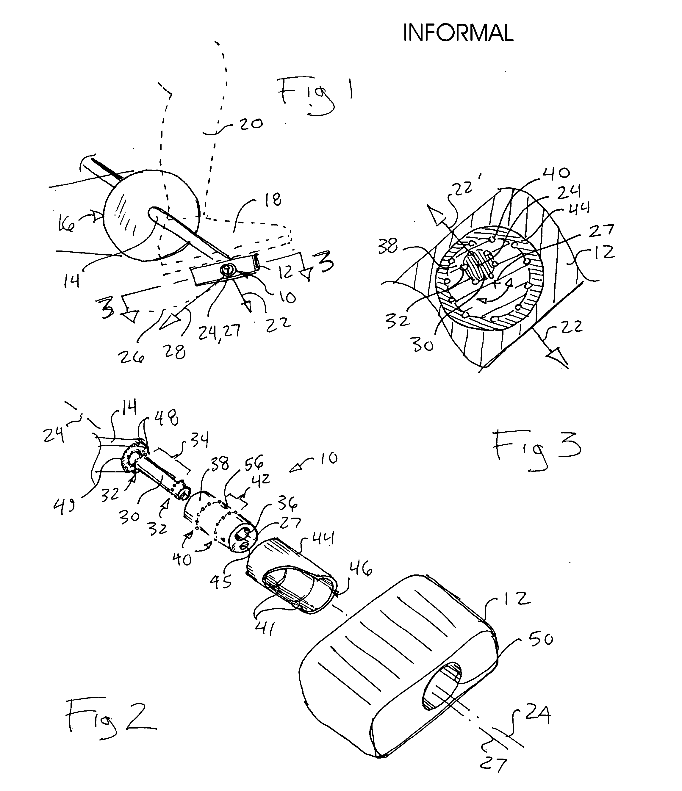
[0033] Referring now to FIG. 1, the present invention provides a force sensor 10 that, in one embodiment, may fit within a pedal 12 of a stationary bicycle or the like. As is understood in the art, the pedal 12 may be attached to a crank arm 14 of a crank assembly 16. The crank assembly 16 also provides a second pedal and crank arm (not shown) so that two pedals may be engaged by a user's feet for exercise of the legs.

[0034] Specifically, a user's foot 18 may press upon the pedal 12 to provide a force 22 shown as a vector having a force angle and first axis 24 through the pedal, and a force magnitude shown as a length of the vector. The pedal 12 is constrained to a circular rotation path 26 by the operation of the crank assembly 16 and motion of the pedal 12 normally requires a component of the force 22 to project along vector 28 tangential to rotation path 26 at the first axis 24, but generally does not require alignment of vectors of forces 22 and 28.

[0035] Referring now to FIG....


PUM


Abstract

An electromechanical force sensor uses a rotating element that aligns with the force and may carry a force magnitude sensor simplifying and providing more accurate measurement of force-angle and force-magnitude. The ability to detect simply force-angle and force-magnitude enables a variety of training and exercise devices.

Description

CROSS-REFERENCE TO RELATED APPLICATIONS STATEMENT REGARDING FEDERALLY SPONSORED RESEARCH OR DEVELOPMENT BACKGROUND OF THE INVENTION [0001] The present invention relates to force sensors, and in particular, to an electromechanical force sensor measuring both force magnitude and angle. [0002] Force sensors, such as strain gauges attached to an elastic carrier, are well known in the art for producing an electrical signal proportional to force. Generally, strain gauges provide a change of resistance as the conductive material of the strain gauge is stretched or compressed. Strain gauges are designed to be sensitive principally along a single axis and will be termed “single axis sensors” producing a magnitude and sign of force in one dimension. [0003] The measurement of force magnitude and direction in two or more dimensions (angle) may be accomplished by placing a number of single axis sensors along different orthogonal axes. Each sensor provides a vector component of the force which ma...

Claims


Application Information

Patent Timeline
IPC IPC(8): G01B7/16
CPCA63B23/0476A63B2220/54B62J2099/002B62K2207/00B62M3/08Y10T74/2168G01L5/0004G01L5/225A63B22/0046A63B22/0605G01L3/242
Inventor GRUBEN, KREG GEORGESCHMIDT, MATTHEW WADE
Owner WISCONSIN ALUMNI RES FOUND
Why Eureka
Try Eureka