

Active cancellation and vibration isolation with feedback and feedfoward control for an aircraft engine mount
- Summary
- Abstract
- Description
- Claims
- Application Information
AI Technical Summary
Benefits of technology
Problems solved by technology
Method used
Image

Examples
Embodiment Construction
[0018] The present invention will be explained in further detail by making reference to the accompanying drawings, which do not limit the scope of the invention in any way.
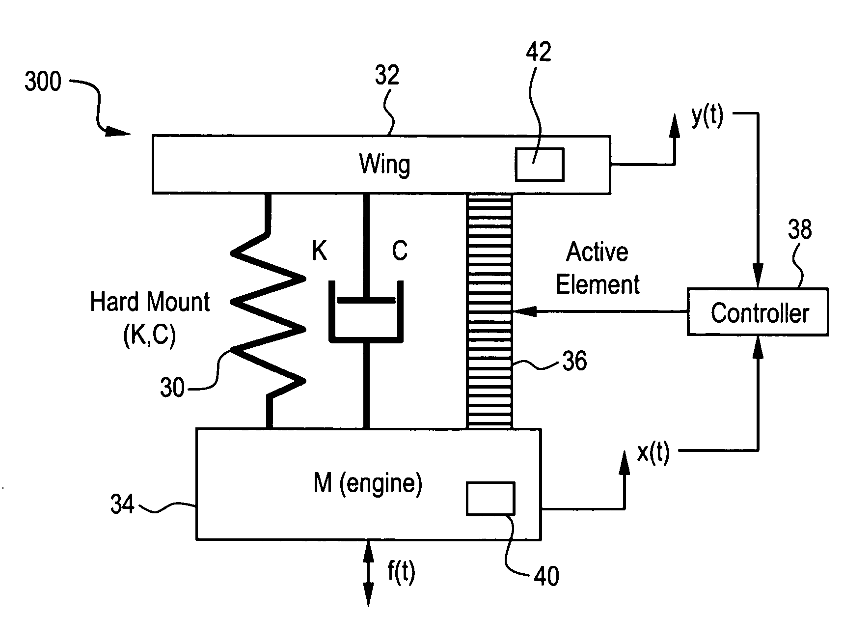
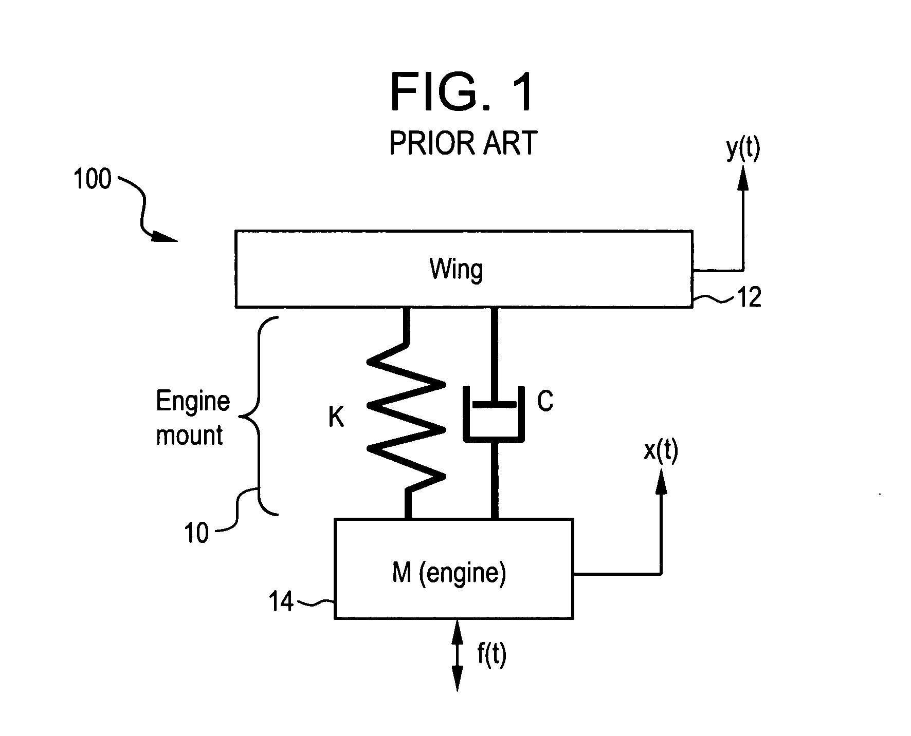
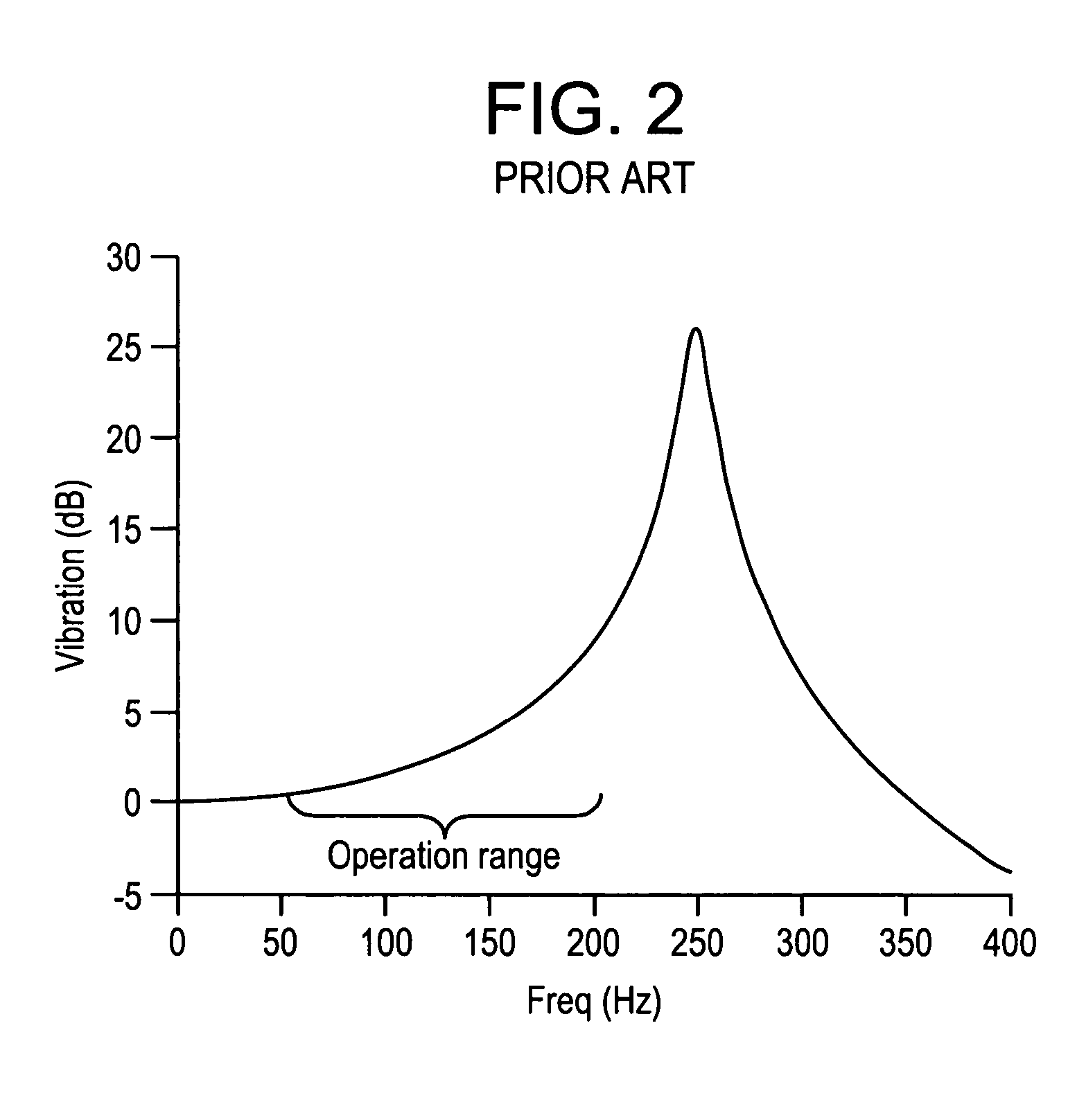
[0019]FIG. 1 depicts a hard engine mount conventionally known, and FIG. 2 shows the transmissibility of the hard engine mount, represented as vibration (dB) v. frequency (Hz). FIG. 3 depicts an engine mount 300 having an active element according to an embodiment of the present invention, while FIG. 5 depicts an engine mount according to an embodiment of the present invention, including a representation of a control system for the engine mount. FIG. 4 depicts the transmissibility (vibration v. frequency) of various engine mount configurations and methods. FIGS. 6 and 7 depict simplified representations of an engine mount to a fuselage and wing, respectively, according to embodiments of the present invention.
[0020] Turning now to FIG. 1, a conventional hard engine mount structure 100 is represented as a single deg...
PUM
 Abstract
Description
Claims
Application Information