Optical encoder
- Summary
- Abstract
- Description
- Claims
- Application Information
AI Technical Summary
Benefits of technology
Problems solved by technology
Method used
Image
Examples
embodiment 1
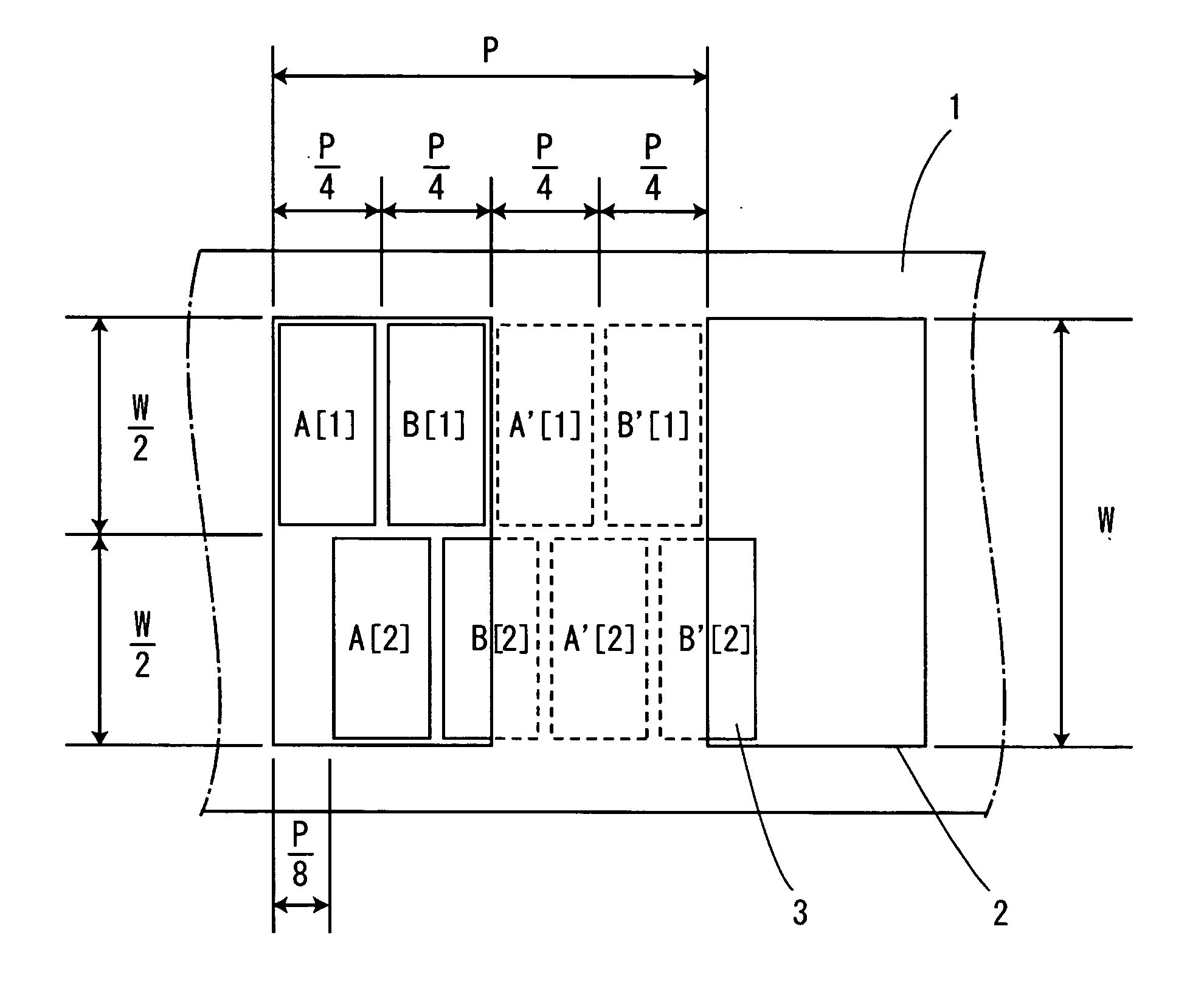
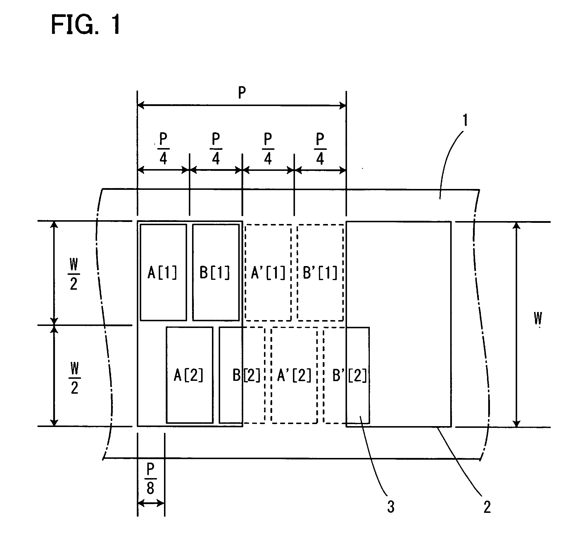
[0036]FIG. 1 shows the configuration of an optical encoder of this embodiment. In a moving section 1, a slit 2 having a width of P / 2 in a moving direction and a width of W in a direction perpendicular to the moving direction is formed every predetermined pitch P in the moving direction.
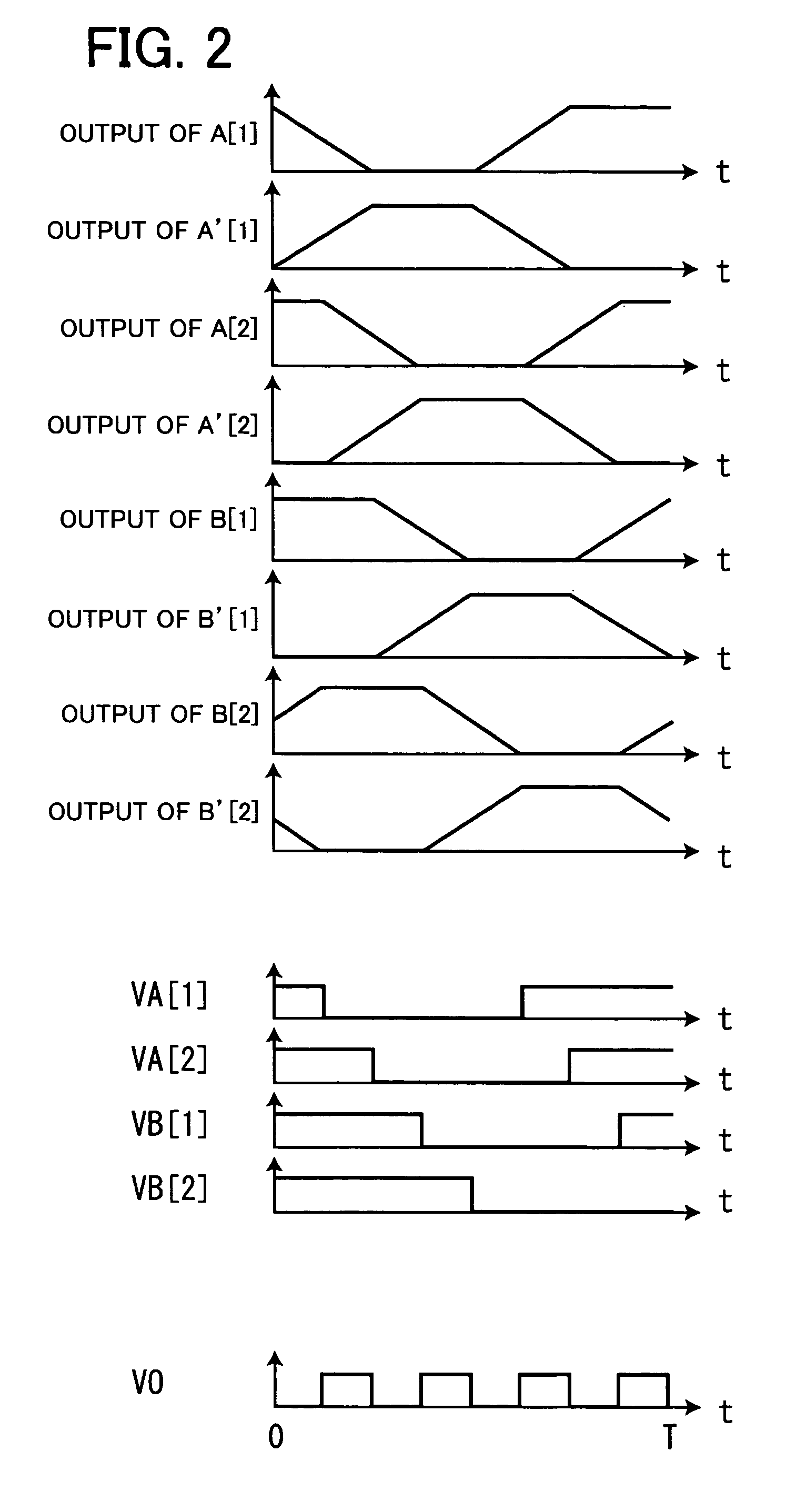
[0037] A light-receiving section is provided with two light-receiving blocks (the respective numerical values in this embodiment correspond to a case where it is assumed that I=1, J=2, M=1 according to fourth aspect). A light-receiving block on a first row in the direction perpendicular to the moving direction is provided with four light-receiving elements 3 (A[1], B[1], A′[1], B′[1]) arranged in series at close intervals in the moving direction and a light-receiving block on a second row in the direction perpendicular to the moving direction is provided with four light-receiving elements 3 (A[2], B[2], A′[2], B′[2]) arranged in series at close intervals in the moving direction. Here, the shape of ea...
embodiment 2
[0040]FIG. 3 shows the configuration of an optical encoder of this embodiment. In a moving section 1, a slit 2 having a width of P / 2 in a moving direction and a width of W in a direction perpendicular to the moving direction is formed every predetermined pitch P in the moving direction.
[0041] A light-receiving section is provided with N (N: integer of 2 or greater) light-receiving blocks (the respective numerical values in this embodiment correspond to a case where it is assumed that I=1, J=N, M=1 according to fourth aspect). When j is assumed to be an integer of 1 or greater and not greater than N, a light-receiving block on a jth row in a direction perpendicular to the moving direction is provided with four light-receiving elements 3 (A[j], B[j], A′[j], B′[j]) arranged in series at close intervals in the moving direction. Here, the shape of each light-receiving element 3 is identical (the width in the moving direction is approximately P / 4 and the width in the direction perpendicu...
embodiment 3
[0044]FIG. 5 shows the configuration of an optical encoder of this embodiment. In a moving section 1, a slit 2 having a width of P / 2 in a moving direction and a width of W in a direction perpendicular to the moving direction is formed every predetermined pitch P in the moving direction.
[0045] A light-receiving section is provided with two light-receiving blocks (the respective numerical values in this embodiment correspond to a case where it is assumed that I=2, J=1, M=1 according to fourth aspect). A light-receiving block on a first row in the moving direction is provided with four light-receiving elements 3 (A[1], B[1], A′[1], B′[1]) and a light-receiving block on a second row in the moving direction is provided with four light-receiving elements 3 (A[2], B[2], A′[2], B′[2]) arranged in series at close intervals in the moving direction. Here, the shape of each light-receiving element 3 is identical (the width in the moving direction is approximately P / 4 and the width in the direc...
PUM
 Abstract
Description
Claims
Application Information
 - R&D
- Intellectual Property
- Life Sciences
- Materials
- Tech Scout
- Unparalleled Data Quality
- Higher Quality Content
- 60% Fewer Hallucinations
Browse by: Latest US Patents, China's latest patents, Technical Efficacy Thesaurus, Application Domain, Technology Topic, Popular Technical Reports.
© 2025 PatSnap. All rights reserved.Legal|Privacy policy|Modern Slavery Act Transparency Statement|Sitemap|About US| Contact US: help@patsnap.com


