Apparatus and method for providing a near-parallel projection from helical scan data

a technology of helical scan data and applicator, applied in the direction of material analysis using wave/particle radiation, instruments, applications, etc., can solve the problems of large amount of computation, difficult interpretation of sp images, and significant additional computation

Active Publication Date: 2007-06-21
MORPHO DETECTION INC
View PDF22 Cites 13 Cited by
  • Summary
  • Abstract
  • Description
  • Claims
  • Application Information

AI Technical Summary

Problems solved by technology

SP images may be difficult to interpret because they are an orthographic projection in one direction (the direction of bag travel), but are a perspective projection in the other direction (across the x-ray fan).
All of these techniques require a very large amount of computation.
This requires significant additional computation, and the resulting projection may not have as much resolution as the original scan data.
A helical scanner produces data that can be used to reconstruct a volume, but does not directly produce a readable projection image.
Reconstruction of the volume, and then creating a projection through the volume as discussed above requires a very large amount of computation, and the result may have limited resolution.

Method used


Image

  • Apparatus and method for providing a near-parallel projection from helical scan data
  • Apparatus and method for providing a near-parallel projection from helical scan data
  • Apparatus and method for providing a near-parallel projection from helical scan data

Examples


Embodiment Construction

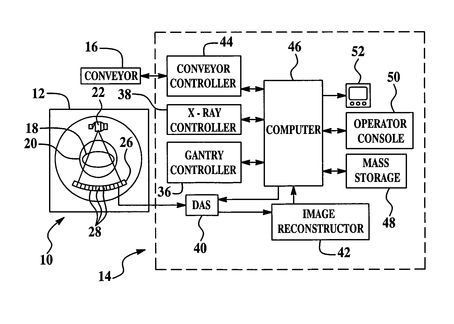
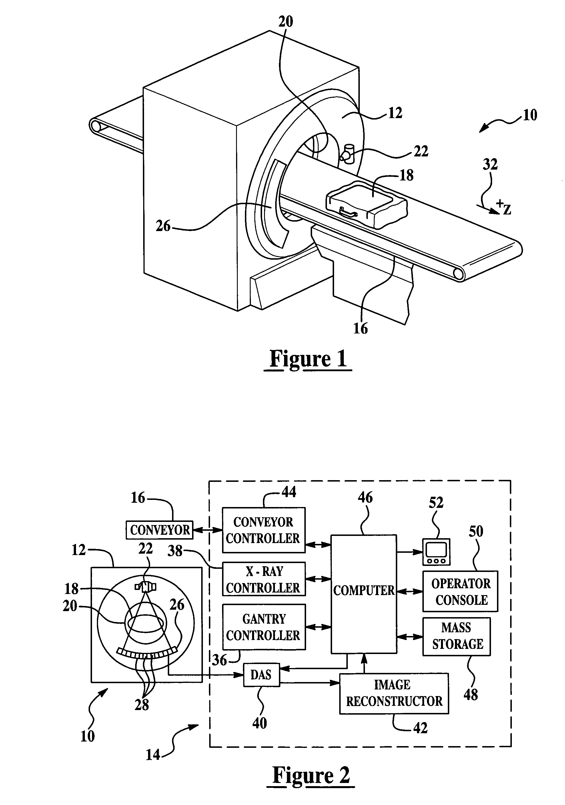
[0023] The disclosure of the present invention relates to an apparatus and method for taking normalized data from a spiral CT scanner and creating a high resolution scan projection image directly from the raw data as opposed to reconstructing the entire volume and making a projection through that volume. The following U.S. Pat. Nos. 5,182,764; 5,367,552; 5,960,056; and 6,647,084, the contents each of which are incorporated herein by reference thereto, provide non-limiting examples of Computed Tomography (CT) Systems.

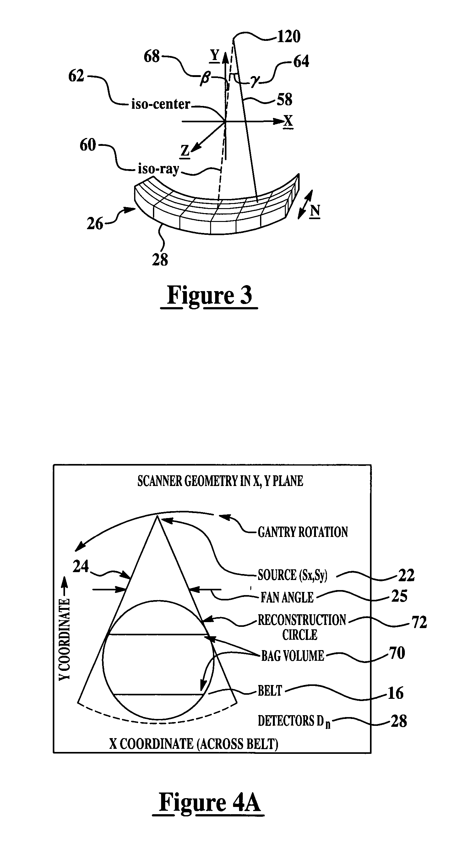
[0024] As used herein, raw data refers to the actual data value read from a detector. The raw data depends on the x-ray intensity at the detector, the gain of the detector, and any bias (offset) that is added to the detector value. Furthermore and as also used herein, offset data, gain data, sample data, Xray intensity, normalized data, converted data, x-ray source position, reconstruction circle, and reconstruction volume are as defined as follows:

[0025] Offset data: ...


PUM

PropertyMeasurementUnit
CTaaaaaaaaaa
volumeaaaaaaaaaa
reconstruction volumeaaaaaaaaaa

Abstract

An apparatus and method for providing a projection image directly from data acquired by a CT scanner, the method comprising: acquiring an amount of data corresponding to an object that is scanned by the CT scanner, wherein the amount of data is generated by an x-ray source that projects a fan beam of x-rays toward a detector array on an opposite side of a gantry of the CT scanner as the object is passed through an opening in the gantry, the acquired amount of data comprising a reconstruction volume; selecting a viewing direction of the object; selecting a portion of a surface intersecting the reconstruction volume, wherein the selected portion comprises an imaging surface inside the reconstruction volume and corresponding to the viewing direction of the object; dividing the imaging surface into a plurality of rows and columns, thus creating a grid of points corresponding to the imaging surface; determining, for each point in the grid, a data point in the acquired amount of data corresponding to an x-ray source position wherein a ray from the x-ray source to the grid point is closest an orientation parallel to the view direction, and a detector position where the ray intersects the detector array; and presenting a projection image corresponding to the selected imaging surface, wherein the projection image comprises a plurality of projection points and each projection point in the projection image is a converted value of the data points of the acquired data.

Description

BACKGROUND [0001] This present invention relates generally to an apparatus and method for scanning and inspecting baggage. More particularly, the present invention relates to an explosive detection system (EDS). [0002] Carry-on and checked baggage inspection systems generally utilize a scan projection (SP) image for presentation to the operator. In most baggage inspection systems, scan projection images are created by moving an object under a fan beam of x-rays from a stationary x-ray source. X-ray intensities, after being attenuated by the object being scanned, are measured by an array of detectors. The x-ray intensity data is converted through a process called normalization so that each pixel represents approximately the total mass traversed by the ray. SP images may be difficult to interpret because they are an orthographic projection in one direction (the direction of bag travel), but are a perspective projection in the other direction (across the x-ray fan). [0003] In some comp...

Claims


Application Information

Patent Timeline
Patent Type & Authority Applications(United States)
IPC IPC(8): H05G1/60A61B6/00G01N23/00G21K1/12
CPCG01T1/2985G01V5/005A61B6/027
Inventor GARMS, WALTERGIROLAMO, UGO DIMERZBACHER, MATTHEW
Owner MORPHO DETECTION INC
Why Eureka
Try Eureka