
Heat exchanger for a diagnostic x-ray generator with rotary anode-type x-ray tube

a technology of x-ray generator and heat exchanger, which is applied in the direction of x-ray tube electrodes, lighting and heating apparatus, coatings, etc., can solve the problem of typical device generated heat insignificant amounts

Active Publication Date: 2007-06-21
ZIEHM IMAGING
View PDF13 Cites 5 Cited by
  • Summary
  • Abstract
  • Description
  • Claims
  • Application Information

AI Technical Summary

Benefits of technology

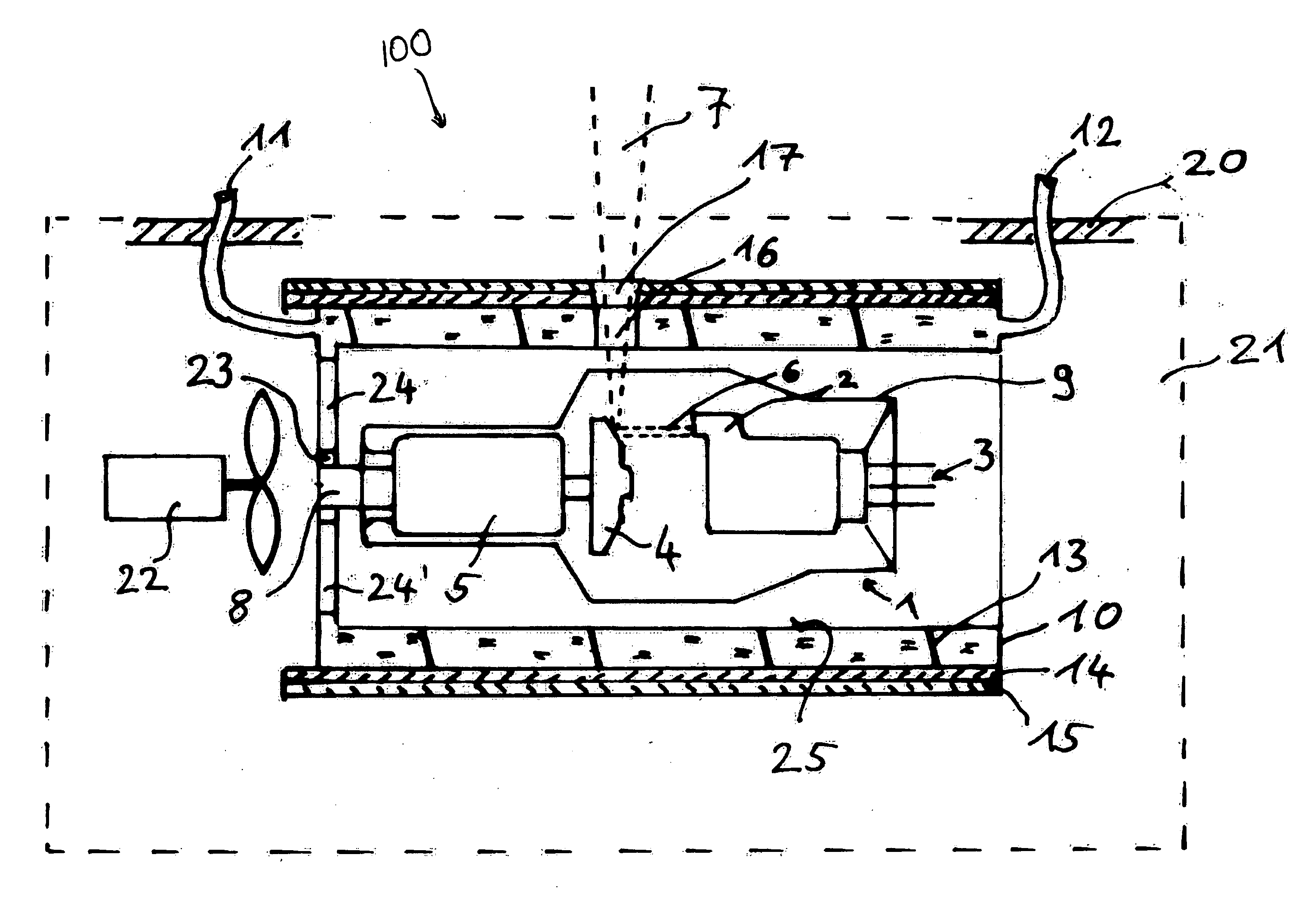
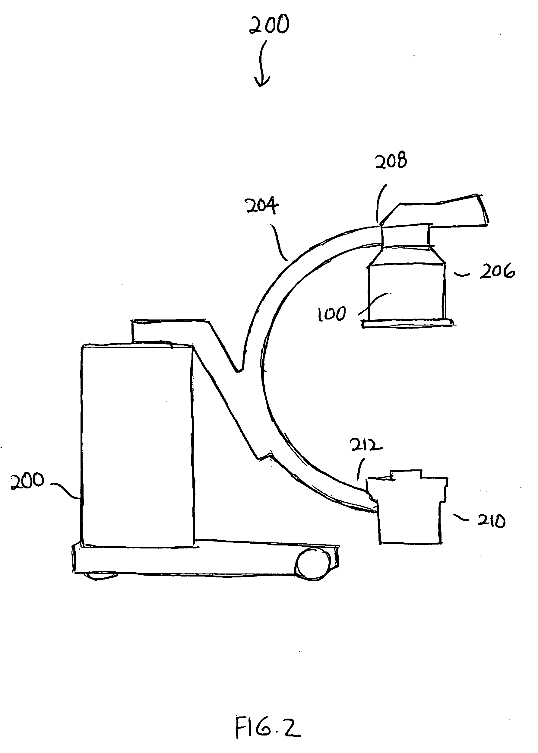
[0008] In one embodiment, the present invention provides an x-ray generator assembly adapted for use in x-ray imaging devices. The x-ray generator assembly comprises a reservoir, a rotary anode x-ray tube disposed in the reservoir, and a heat exchanging system. In one embodiment, the heat exchanging system comprises an enclosure wherein the enclosure is adapted to enclose the rotary anode x-ray tube, wherein the enclosure comprises a double wall defining a conduit for a cooling fluid to flow therethrough. In a preferred embodiment, the cooling fluid is circulated through the conduit defined by the double wall to remove heat generated from the rotary anode x-ray tube. In another preferred embodiment, a plurality of cut-outs are formed in the enclosure to permit transmission of a portion of the x-ray radiation generated by the x-ray generator to a location external to the generator. In yet another embodiment, a shield is formed on an exterior surface of the enclosure of the heat exchanger, wherein the shield is adapted to inhibit transmission of a second portion of the x-ray radiation generated by the generator. In yet another embodiment, the cooling fluid inside the heat exchanger is disposed about 20 mm or less from the rotary anode tube. In one implementation, the x-ray generator assembly is incorporated in a C-arm x-ray imaging system.
[0009] In another embodiment, the present invention provides a heat exchanger for an

Problems solved by technology

During operation, significant amount of heat is typically generated by the device.

Method used


Image

  • Heat exchanger for a diagnostic x-ray generator with rotary anode-type x-ray tube
  • Heat exchanger for a diagnostic x-ray generator with rotary anode-type x-ray tube
  • Heat exchanger for a diagnostic x-ray generator with rotary anode-type x-ray tube

Examples


Embodiment Construction

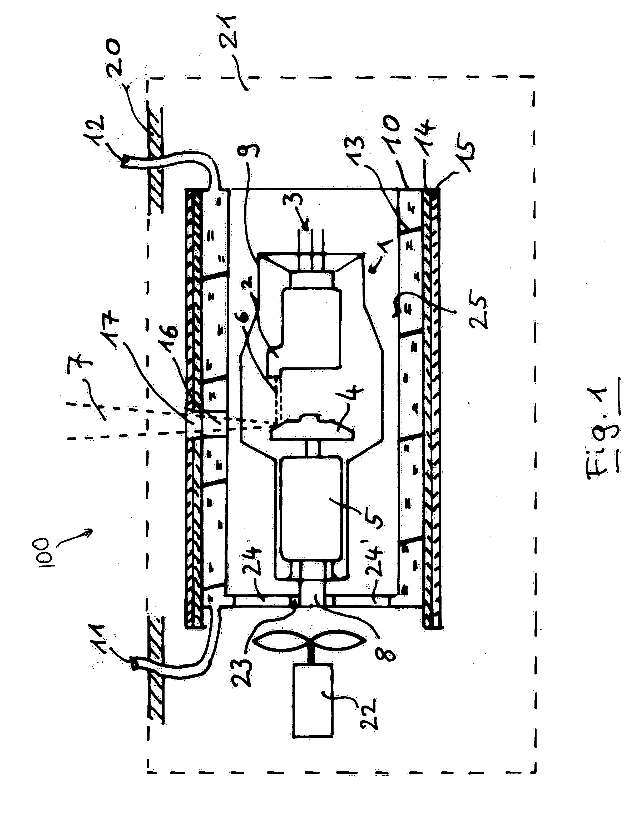
[0012]FIG. 1 is a schematic diagram of a cross-section view of an x-ray generator system 100 of one preferred embodiment of the present invention. The system 100 incorporates a novel heat exchanger system, which is designed to facilitate the dissipation of heat generated by a rotary anode tube so as to inhibit substantial heat from being transferred to the surrounding electronic components. As shown in Figure, the system 100 generally includes a generator tank or reservoir 20 that is filled with oil 21, a pump 22 adapted to circulate the oil 21, a rotary anode tube 1 disposed in the tank 20, and a heat exchanger system 10 that is positioned adjacent to the rotary anode tube 1 in the tank 20. The rotary anode tube 1 comprises an evacuated glass jacket 9 through which cathode connections 3 and anode connections are passed. The rotary anode tube 1 further includes an electron gun 2, an anode plate 4, and a rotary anode drive 5. An electron beam 6 generated in the electron gun 2 impinge...


PUM

PropertyMeasurementUnit
Lengthaaaaaaaaaa
Distanceaaaaaaaaaa

Abstract

A heat exchanger system for a single-tank x-ray generator of an x-ray diagnostic device with a rotating anode tube with a glass jacket is provided. The system provides for the thermal radiation emitted by the anode plate of the rotating anode tube, which glows during load operation, to be absorbed in very close proximity to the tube by a heat exchanger with a window for the exiting x-ray radiation beam, without causing other components inside the generator tank to be heated by the thermal radiation. The heat exchanger preferably includes the lead shield required to shield against x-ray back-radiation and has a cooling agent flowing through it. The layer of insulating oil present in the space between the rotating anode tube and the heat exchanger is exchanged by means of a pump against insulating oil from other areas of the tank so as to prevent local overheating of the insulating oil in the gap.

Description

CROSS-REFERENCE TO RELATED APPLICATIONS [0001] This application claims the benefit of priority of German Patent Application No. DE102005049455.2 filed on Sep. 27, 2005, which is hereby incorporated by reference in its entirety. BACKGROUND OF THE INVENTION [0002] 1. Field of the Invention [0003] The present invention generally relates to cooling systems for x-ray diagnostic devices, and in particular, relates to a heat exchanger system for an x-ray generator with a rotary anode x-ray tube. [0004] 2. Description of the Related Art [0005] X-ray diagnostic devices frequently incorporate single-tank generators in which the x-ray source and high voltage generating components are combined into one structural unit. During operation, significant amount of heat is typically generated by the device. Various heat exchanger systems for cooling oil-filled single-tank generators are known. Examples of heat exchangers developed for mobile x-ray apparatus are described in Applicant's co-pending Germ...

Claims


Application Information

Patent Timeline
IPC IPC(8): H01J35/00
CPCF28F13/125F28F13/18F28F2245/06
Inventor HORNDLER, KLAUSSCHWARZBAUER, PETERGUNTHER, MICHAEL
Owner ZIEHM IMAGING
Learn More