Method and apparatus of producing stator

Inactive Publication Date: 2007-06-28
TOYOTA IND CORP +1
View PDF0 Cites 20 Cited by
  • Summary
  • Abstract
  • Description
  • Claims
  • Application Information

AI Technical Summary

Benefits of technology

[0037] According to the above-mentioned producing apparatus, one side of each of the plurality of coils is projected outside the jig, and the other side of each of the plurality of prepared coils is inserted into the holding groove group, each coil is arranged along the circumference of the jig, an auxiliary member having a plurality of blade portions provided corresponding to one or more inner teeth of the stator core is mounted on the end surface of the jig, one side of each of the plurality of prepared coils is held in the space between the corresponding blade portions, and the jig is inserted from the auxiliary member side into the inner circumference of the stator core, and guiding one side of each of the plurality of prepared coils by the auxiliary member, and pushing the side into the corresponding slot of

Problems solved by technology

However, in these methods, only a coil obtained by concentrically winding wire on each magnetic pole can be formed.
However, the above-mentioned spiral coil stator has to be generated by inserting each of both sides of a coil into a slot one by one with another coil overlap each other, and it is hard to mechanically perform the process.
Therefore, it is necessary to manually insert a prepared coil into the slot of a

Method used


Image

  • Method and apparatus of producing stator
  • Method and apparatus of producing stator
  • Method and apparatus of producing stator

Examples


Example

[0068] The mode for embodying the present invention is explained below by referring to the attached drawings

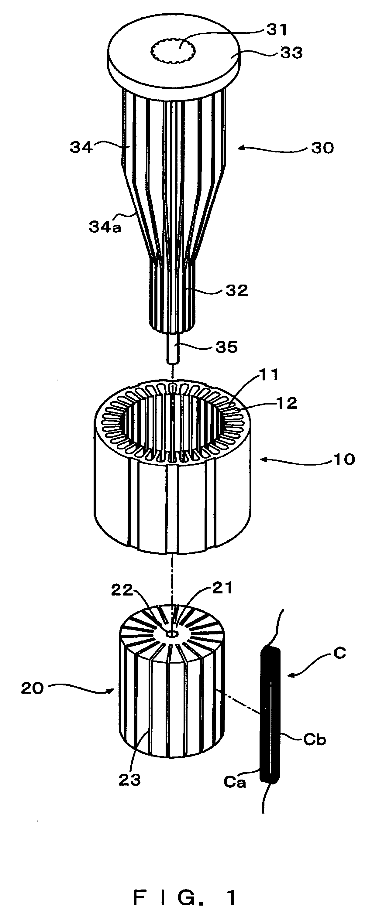
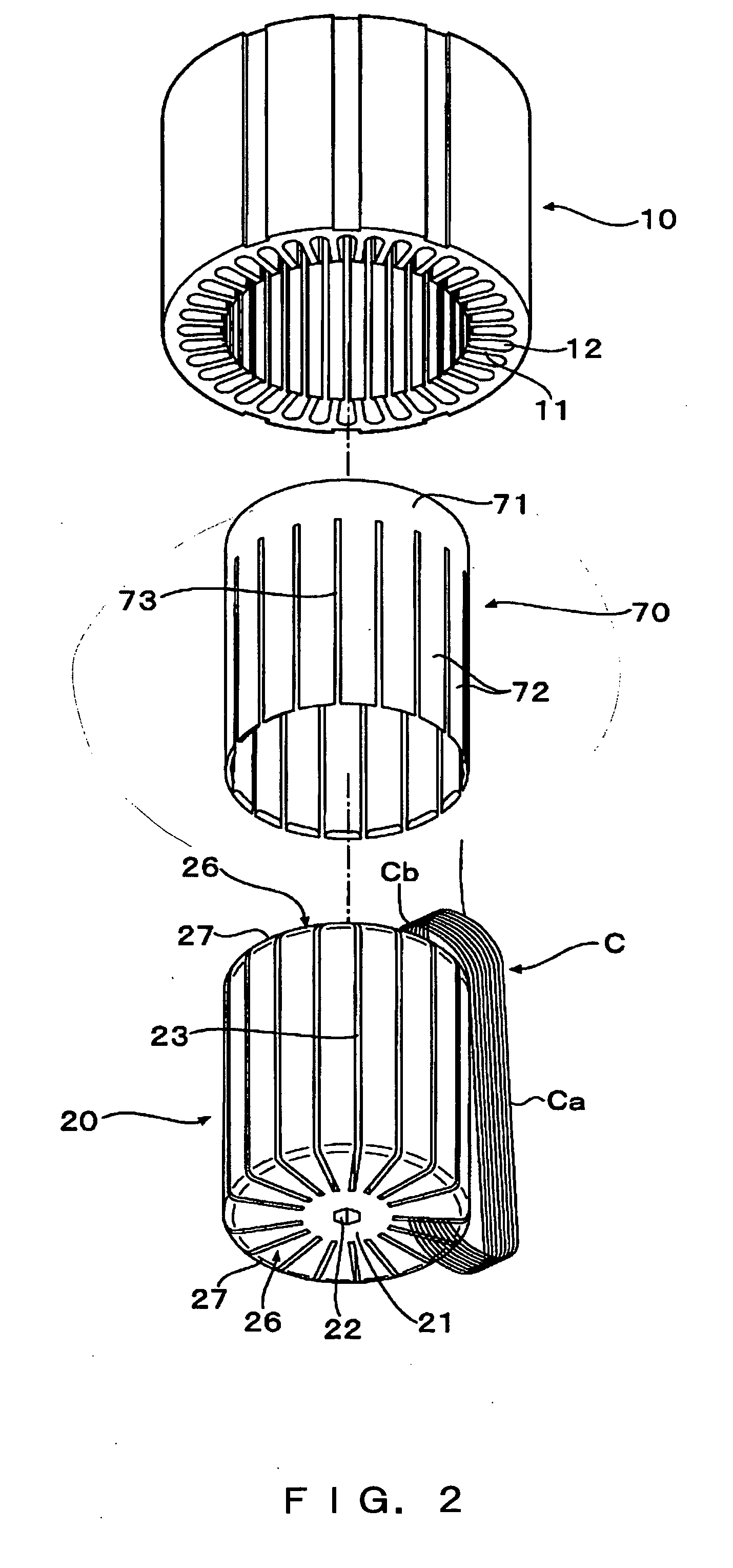
[0069]FIGS. 1 and 2 show a mode for embodying the apparatus for producing a stator according to the present invention.

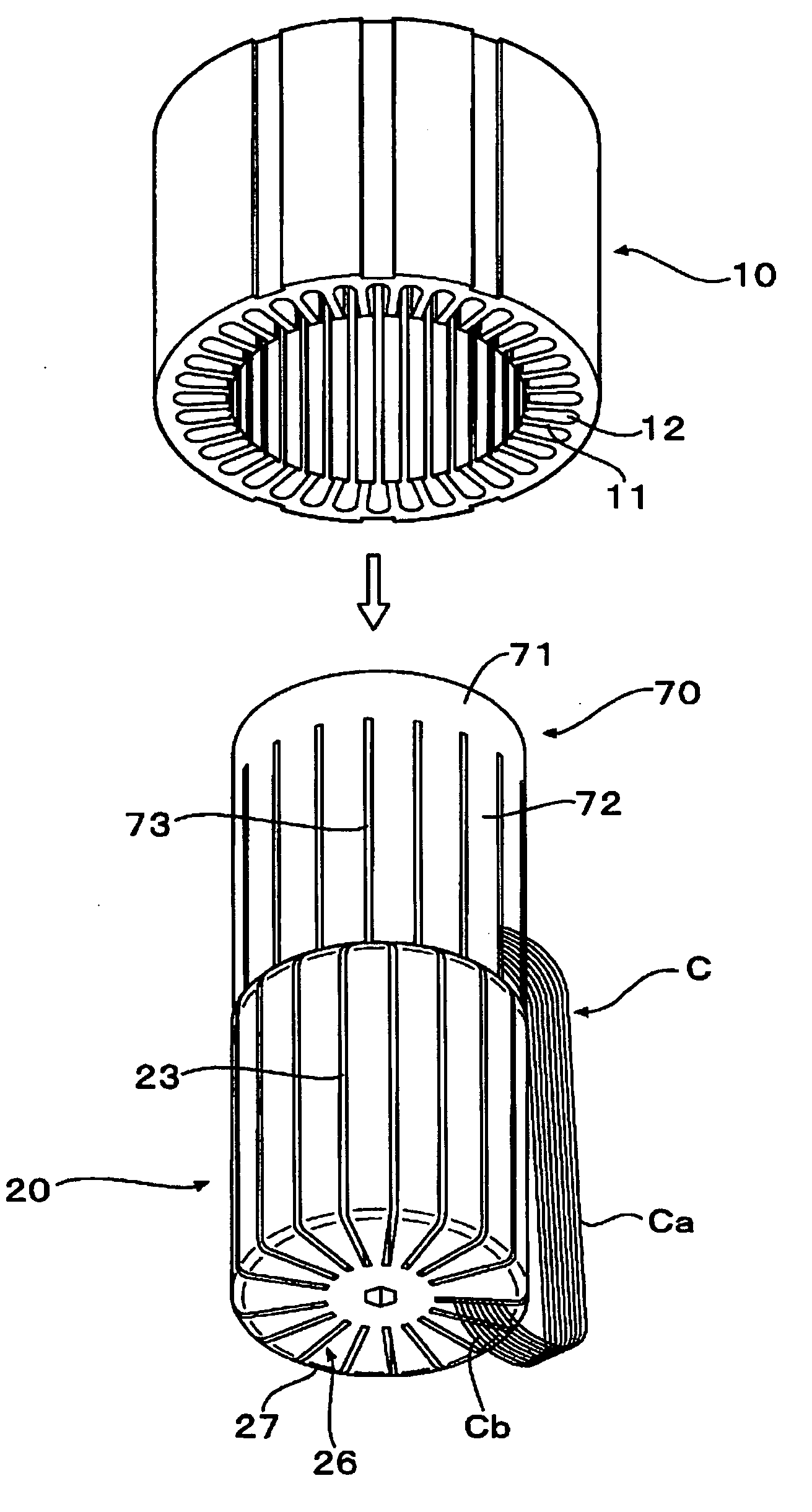
[0070] In FIGS. 1 and 2, a stator core 10 has an inner tooth 11 at the inner circumference, and a slot 12 is formed between the inner teeth 11.

[0071] The producing apparatus has a substantially cylindrical jig 20 inserted inside the inner circumference of the stator core 10. The jig 20 has a central axis portion 21, a hole 22 provided at the center of the top surface of the axis portion 21, and a plurality of holding grooves 23 radially formed from the outer circumference of the axis portion 21 from the outer circumference of the axis portion 21 toward the outer circumference of the cylindrical jig.

[0072] The holding groove 23 is formed with pitches of integral multiple pitches of the slot 12 of the stator core 10. In this mode for embodying the present inv...


PUM

PropertyMeasurementUnit
Frequencyaaaaaaaaaa
Forceaaaaaaaaaa
Magnetic fieldaaaaaaaaaa

Abstract

Using a jig having on its outer circumference a holding groove group formed by a plurality of slit-shaped holding grooves with pitches of integral multiple pitches of a slot of a stator core, one side of each coil is projected outside the jig, the other side of each coil is inserted into the holding groove group, an auxiliary member having a plurality of blade portions are provided at the end surface of the jig, the jig is inserted into the inner circumference of the stator core from the auxiliary member side, one side of each coil is pushed into a corresponding slot of the stator core, thus the jig is rotated and positioned such that the holding groove can match the corresponding slot of the stator core, and the push out device inserts the other side of each coil into a corresponding slot.

Description

BACKGROUND OF THE INVENTION [0001] 1. Field of the Invention [0002] The present invention relates to a method and an apparatus of producing a stator by inserting one sides of a plurality of prepared coils into the slot of a stator core, inserting the other sides of the plurality of prepared coils into another slot, and spirally combining the coils as viewed from the one side of the stator core. [0003] 2. Description of the Related Art [0004] As a method of producing a stator having a prepared coil can be a method of directly winding wire on the inner teeth of a stator core and a method of inserting a prepared coil into a slot of a stator core. [0005] However, in these methods, only a coil obtained by concentrically winding wire on each magnetic pole can be formed. Therefore, a motor using such a stator core causes a nonuniform torque by a phenomenon in which the density of a circular magnetomotive force is nonuniform. Since the nonuniform torque causes the vibration and noise of a m...

Claims


Application Information

Patent Timeline
IPC IPC(8): H02K15/00
CPCH02K15/005H02K15/066Y10T29/49009Y10T29/53143Y10T29/49012H02K15/067
Inventor YAMAGUCHI, KAZUYUKIKATO, YOSHIO
Owner TOYOTA IND CORP
Why Eureka
Try Eureka