Hydraulic damper for vehicle

Inactive Publication Date: 2007-06-28
SOQI HS
View PDF10 Cites 8 Cited by
  • Summary
  • Abstract
  • Description
  • Claims
  • Application Information

AI Technical Summary

Benefits of technology

[0021] This invention is adapted to be embodied in a suspension system for a vehicle supporting element for movement in jounce (compression) and rebound (expansion

Problems solved by technology

Generally the type of hydraulic damper utilized for this purpose is not sufficiently responsive to changes from compression damping as occurs during “jounce” and expansion damping as occurs during “rebound”.
In addition because of the types of construction normally employed, insufficient damping from that desired must be accepted.
However, since the oil acting to produce contraction side damping force is used only in the amount corresponding to the cross-sectional area of the piston rod 24, the flow rate is small and the damping force on the con

Method used


Image

  • Hydraulic damper for vehicle
  • Hydraulic damper for vehicle
  • Hydraulic damper for vehicle

Examples


Embodiment Construction

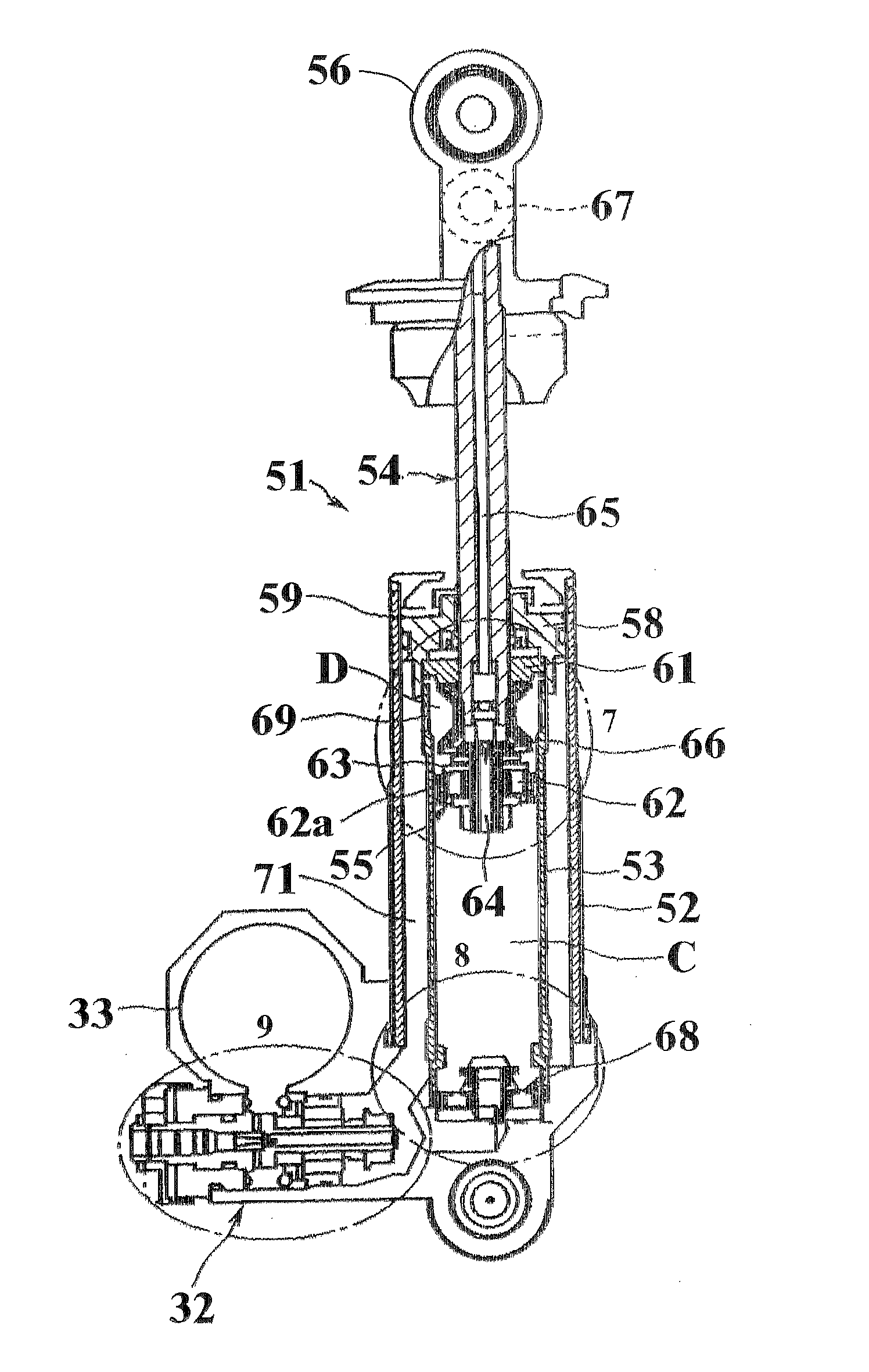
[0042] Referring now in detail to the drawings and initially to FIG. 6, a hydraulic damper embodying the invention is indicated generally by the reference numeral 51. The damper 51 includes an outer housing comprised of coaxially disposed inner and outer cylinders 52 and 53 of different diameters. A piston rod 54 is inserted to be axially movable in the inner cylinder 53.

[0043] A piston 55 is fixed to the lower end of the piston rod 54 to divide the interior of the inner cylinder 53 into a contraction side oil chamber C oil the lower end side of the piston 55 and an expansion side oil chamber D on the back side of the piston 55. The fore-end portion of the hydraulic damper 51 has a portion 56 configured for connection to a vehicle supporting component for example a wheel support member (not shown). The upper end portion 57 of the piston rod 54 is connected to a vehicle body (not shown).

[0044] A base member 58 is inserted in the base end side of the outer cylinder 52 and fixed in po...


PUM


Abstract

An improved fluid damping unit of the piston cylinder type that provides substantially equal damping in each direction and improved damping by displacing the full cross sectional area of the piston in each direction and quicker response upon reversal between jounce and rebound.

Description

BACKGROUND OF THE INVENTION [0001] This invention relates to a hydraulic damper for damping both the contraction and expansion of a vehicle ground supporting element such as, by way of example a wheel. [0002] Generally the type of hydraulic damper utilized for this purpose is not sufficiently responsive to changes from compression damping as occurs during “jounce” and expansion damping as occurs during “rebound”. In addition because of the types of construction normally employed, insufficient damping from that desired must be accepted. [0003] For example, a conventional prior art type damper is shown in FIGS. 1 and 2. For example, a hydraulic damper for the rear wheel of motorcycles is disclosed in Japanese Published Patent Document JP-A-Hei 6-127453. [0004]FIG. 1 is a sectional view of a prior art hydraulic dampers indicated generally by the reference numeral 21 for the rear wheel of motorcycles. The damper 21 is comprised of an outer cylinder 22 in which a piston 23 is fitted to d...

Claims


Application Information

Patent Timeline
IPC IPC(8): F16F9/00
CPCF16F9/061F16F9/064F16F9/342F16F9/504
Inventor SAITO, TAKUYA
Owner SOQI HS
Why Eureka
Try Eureka