
Monitoring status of railyard equipment using wireless sensing devices

a technology of wireless sensing and status monitoring, applied in the direction of anti-theft devices, process and machine control, instruments, etc., can solve the problems of insufficient remote control of switches, no presently existing technology provides inexpensive automated communication, and complex operation of managing the entire railyard efficiently

Inactive Publication Date: 2007-06-28
GENERAL ELECTRIC CO
View PDF16 Cites 17 Cited by
  • Summary
  • Abstract
  • Description
  • Claims
  • Application Information

AI Technical Summary

Benefits of technology

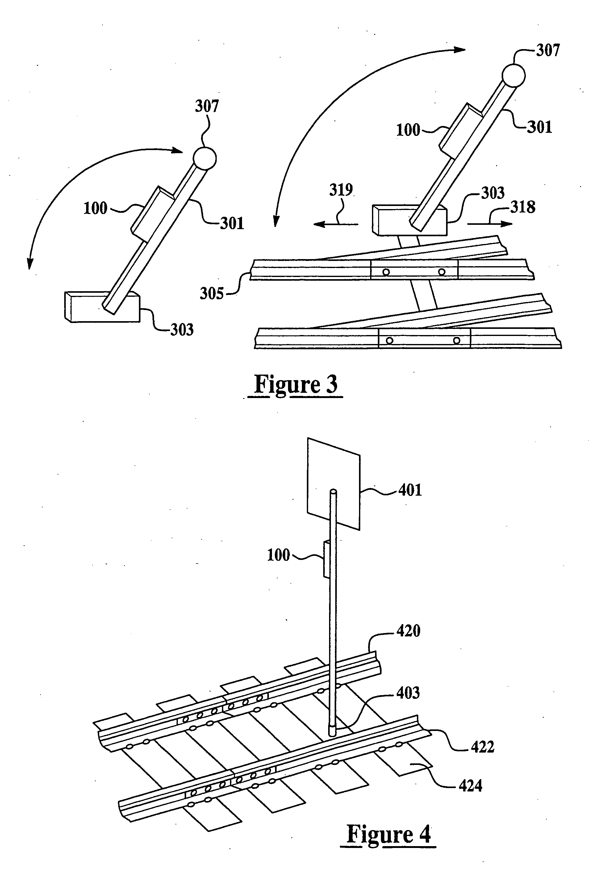
[0008] Pursuant to one set of embodiments, a wireless position sensing device is provided for monitoring railyard equipment status. The device comprises a gravity sensing mechanism for sensing an angular displacement with respect to a substantially vertical line, and for generating a displacement signal upon sensing a change in angular displacement exceeding approximately 40 degrees. A processing mechanism, operatively coupled to the gravity sensing mechanism, receives the displacement signal. A radio frequency transmitter, responsive to the processing mechanism, transmits a data signal indicative of the angular displacement. The processing mechanism is programmed to activate the radio frequency transmitter upon receipt of the displacement signal. The gravity sensing mechanism is affixed, attached, or mechanically coupled to railyard equipment comprising at least one of a manually operated rail switch or a safety indicator.
[0009] Pursuant to another set of embodiments, a wireless magnetic sensing device is provided for monitoring railyard equipment status. The device comprises a magnetic sensing mechanism for sensing an applied magnetic field, and for generating a detection signal upon sensing of the applied magnetic field. A processing mechanism, operatively coupled to the magnetic sensing mechanism, receives the detection signal. A radio frequency transmitter, responsive to the processing mechanism, transmits a data signal indicative of the sensing of the applied magnetic field. The processing mechanism is programmed to activate the radio frequency transmitter upon receipt of the detection signal. The magnetic sensing mechanism is affixed, attached, or mechanically coupled to railyard equipment comprising at least one of a rail tie, a safety indicator, or a safety indicator receptacle.
[0010] Pursuant to another set of embodiments, a wireless magnetic sensing system is provided for monitoring railyard equipment status. The system comprises a wireless magnetic sensing device including: (i) a magnetic sensing mechanism for sensing an applied magnetic field, and for generating a detection signal upon sensing of the applied magnetic field; (ii)

Problems solved by technology

The various services in a railyard compete for resources such as personnel, equipment, and space in various facilities so that managing the entire railyard efficiently is a complex operation.
No presently existing technique provides inexpensive automated communication of blue flag indicator status or switch position status to a remote monitoring location.
Switch position status is not communicated to a centralized monitoring location unless that switch is a remotely controlled switch, whereas many presently existing railyard switches are not equipped for remote control.
However, digging a conduit trench in a rail yard is complicated by the constant movement of railcars, as well as by the hard-packed earth and track beds.
Trenching of cables in a rail yard is an expensive and time consuming activity which adversely impacts railyard operations and the free movement of railcars.
Although a limited number of specially configured railyard switches use wireless communication for remotely controlling the position of the switch, a relatively large number of existing conventional railyard switches do not have wireless sensing capability, and cannot be easily modified to include this capability.
This switch replacement process is tedious, labor intensive, and expensive.

Method used


Image

  • Monitoring status of railyard equipment using wireless sensing devices
  • Monitoring status of railyard equipment using wireless sensing devices
  • Monitoring status of railyard equipment using wireless sensing devices

Examples


Embodiment Construction

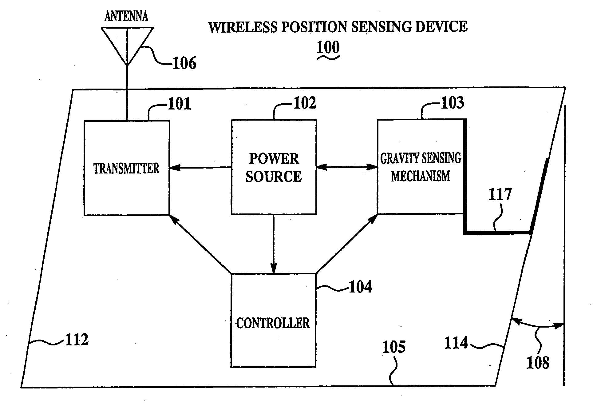
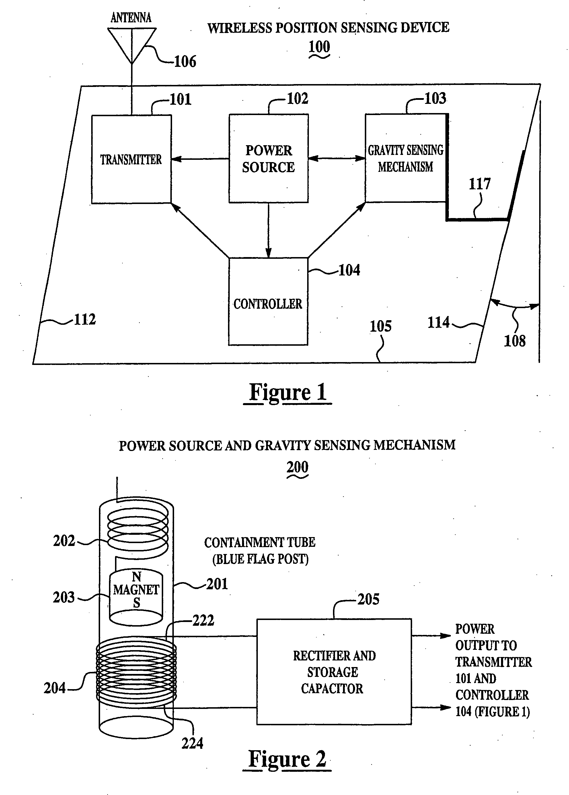
[0018]FIG. 1 is a block diagram of a wireless position sensing device 100 for monitoring status of railyard equipment from a remote location in accordance with a set of embodiments of the present invention. A power source 102 provides power to a transmitter 101, a controller 104, and a gravity sensing mechanism 103. Transmitter 101 is coupled to an antenna 106. A device casing 105 at least partially encases one or more of gravity sensing mechanism 103, controller 104, transmitter 101 and, optionally, power source 102. Power source 102 may be implemented using batteries, solar cells, a gravity-based power supply, a self-powered supply, other types of power sources, or any of various combinations thereof. For example, energy harvesting techniques may be used to provide supplemental power to trickle-charge a small battery, thus allowing for a reduction in required battery size and weight, or an extension of the battery life, or both.

[0019] Gravity sensing mechanism 103 is affixed to d...


PUM


Abstract

A wireless position sensing device is provided for monitoring railyard equipment status. The device comprises a gravity sensing mechanism for sensing an angular displacement with respect to a substantially vertical line, and for generating a displacement signal upon sensing a change in angular displacement exceeding approximately 40 degrees. A processing mechanism, operatively coupled to the gravity sensing mechanism, receives the displacement signal. A radio frequency transmitter, responsive to the processing mechanism, transmits a data signal indicative of the angular displacement. The processing mechanism is programmed to activate the radio frequency transmitter upon receipt of the displacement signal. The gravity sensing mechanism is affixed, attached, or mechanically coupled to railyard equipment comprising at least one of a manually operated rail switch or a safety indicator.

Description

BACKGROUND [0001] This invention relates generally to railyard equipment and, more particularly, to monitoring the status of railyard equipment from a remote location. [0002] Railyards are the hubs of railroad transportation systems. Therefore, a broad spectrum of services are provided at railyards, including freight origination, interchange and termination, locomotive storage and maintenance, assembly and inspection of new trains, servicing of trains running through the facility, inspection and maintenance of railcars, and railcar storage. The various services in a railyard compete for resources such as personnel, equipment, and space in various facilities so that managing the entire railyard efficiently is a complex operation. [0003] In order to improve the efficiency of railyard operations, it would be useful to monitor railyard equipment, such as blue flag indicators, rail switches, signaling equipment, and the like, from a remote location. A typical railyard may include hundred...

Claims


Application Information

Patent Timeline
IPC IPC(8): G08B21/00G08B1/08
CPCB61L5/02B61L5/107B61L5/125B61L17/023
Inventor WELLES, KENNETH BRAKELEYBHOTIKA, RAHULDAVENPORT, DAVID MICHAELHERSHEY, JOHN ERIKMITCHELL, ROBERT JAMESANDARAWIS, EMAD ANDARAWIS
Owner GENERAL ELECTRIC CO
Learn More